Image diagnosis apparatus for medical purpose

A diagnostic equipment and medical image technology, applied in the direction of diagnosis, application, medical science, etc., can solve the problems of space occupation, failure to achieve optimization, and limitation of the space layout of the main body of the equipment.

Inactive Publication Date: 2008-04-02
KK TOSHIBA +1
View PDF1 Cites 6 Cited by
  • Summary
  • Abstract
  • Description
  • Claims
  • Application Information

AI Technical Summary

Problems solved by technology

[0006] However, in this kind of device, because the spring device, especially the booster device such as the gas spring, is placed in the frame of the device body, it needs to occupy a certain space, so that the spatial arrangement of the device body is limited. In terms of labor saving, it has not reached the optimum

Method used


Image

  • Image diagnosis apparatus for medical purpose
  • Image diagnosis apparatus for medical purpose
  • Image diagnosis apparatus for medical purpose

Examples


Embodiment Construction

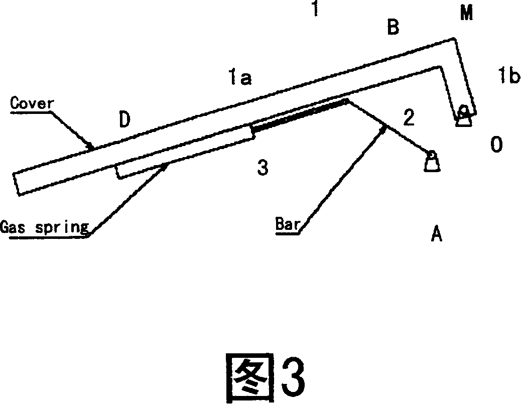
[0024] As shown in FIG. 3 , the box structure of the medical imaging diagnostic equipment of the present invention has: a frame body (not shown) as the body body of the box body; and a cover 1 that can be opened and closed relative to the frame body. It also has: a pillar 2, which is connected to the above-mentioned frame body through the first rotating shaft (A); a telescopic mechanism 3, which is installed on the cover 1, one end of which is fixed on the cover (D), and the other end (B) is for example passed through A rotating shaft is connected to the other end of the strut. Here the telescopic mechanism is a spring device, such as a gas spring.

[0025] Fig. 13 shows a perspective view of the medical image diagnosis device of the present invention.

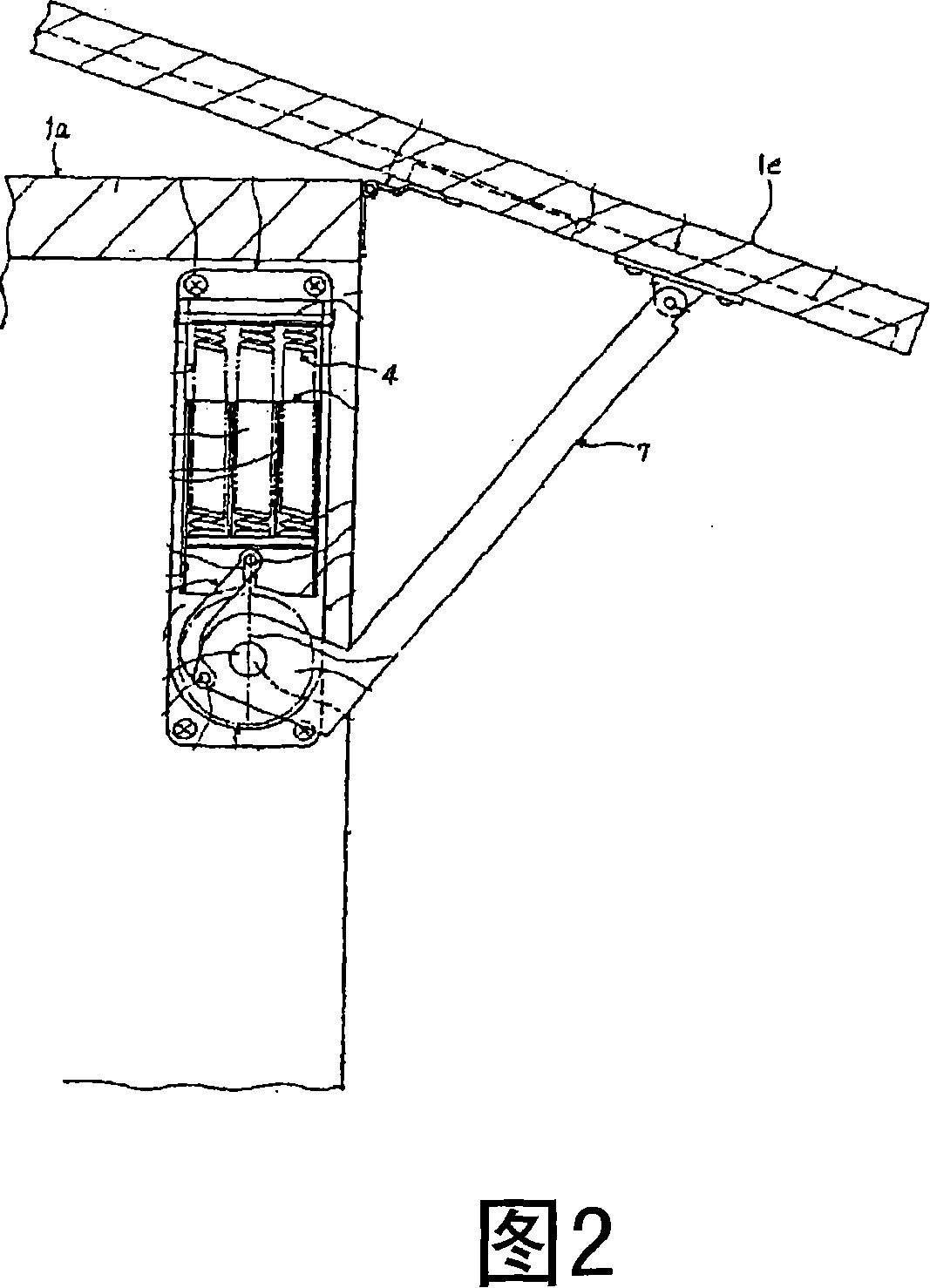
[0026] As for the setting of the telescoping mechanism on the cover, as shown in Figure 4, one end of the spring device is fixed on the cover; the other end is used as a movable end and connected to the other end of the suppo...


PUM


Abstract

The present invention provides an assistant mechanism for large scale equipments such as medical image diagnostic equipment, which is capable of enlarging useful space of an equipment main body, playing a function of saving labor and opening a cover conveniently, and optimizing effort distribution for opening a cover. A medical image diagnostic equipment of the invention comprises a frame body, a cover that can be closed in relative to the frame body; a support column, one end of which is connected with the frame body through a first rotation axis; an extensible mechanism which is set along with the cover, one end of the extensible mechanism is connected with another end of the support column.

Description

technical field [0001] The present invention relates to a case structure of large-scale equipment such as medical image diagnostic equipment, and more particularly, to a structure that can easily open the cover of such medical image diagnostic equipment. Background technique [0002] For large box structures such as medical imaging diagnostic equipment and automobiles, as shown in Figure 1, when opening the back cover, the operator needs to lift the cover upwards. For heavy covers (for example, greater than 20kg) and the height of the cover rotation fulcrum is high Due to the height of the device, it is difficult to open the cover to 90° by one person alone, and two people need to stand on both sides of the device to open the cover to 90° together, and then support the cover with a pole. [0003] In particular, for a large-scale device such as an X-ray CT diagnostic device, a worker needs to open the front cover of the device in order to inspect the inside of the device. At...

Claims


Application Information

Patent Timeline
Patent Type & Authority Applications(China)
IPC IPC(8): A61B19/02A61B6/03G12B9/04
CPCE05Y2201/478E05F1/1091A61B6/035
Inventor 魏玮
Owner KK TOSHIBA
Why Eureka
Try Eureka