Flange fabrication method for hollow concrete pile

A technology of hollow concrete and flanges, which is applied in building construction, foundation structure engineering, sheet pile walls, etc., can solve problems such as complicated procedures and high manufacturing costs, and achieve the effect of preventing damage or breaking and strengthening rigidity

Inactive Publication Date: 2008-04-02
金海权
View PDF0 Cites 1 Cited by
  • Summary
  • Abstract
  • Description
  • Claims
  • Application Information

AI Technical Summary

Problems solved by technology

[0007] However, the traditional flange manufacturing process is complicated, and in order to improve the rigidity of the flan...

Method used


Image

  • Flange fabrication method for hollow concrete pile
  • Flange fabrication method for hollow concrete pile
  • Flange fabrication method for hollow concrete pile

Examples


Embodiment Construction

[0024] Preferred embodiments of the present invention will be described in detail below with reference to the accompanying drawings.

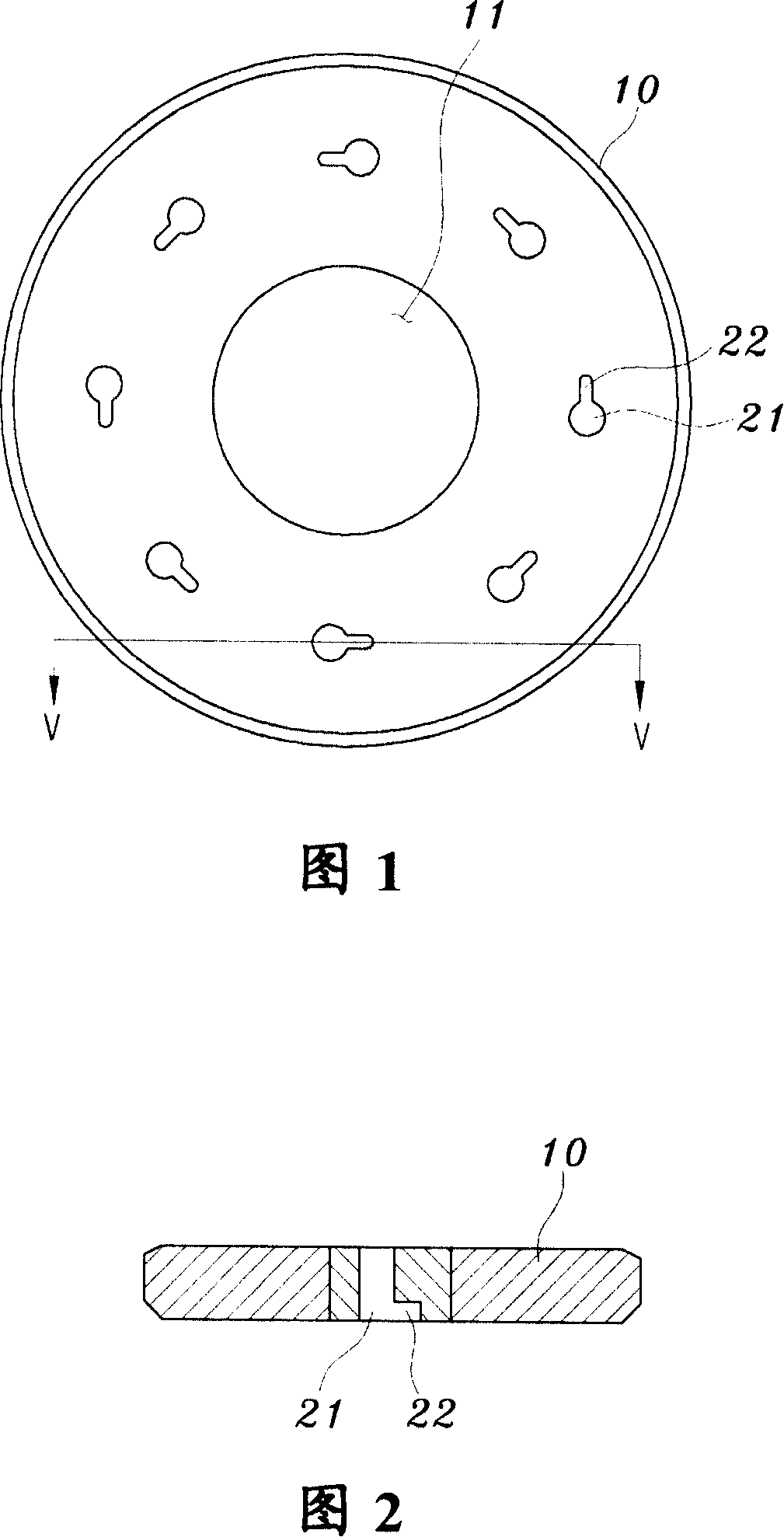
[0025] In the description of the present invention, the description shall be based on the drawings. The vertical direction is drawn based on the horizontal line of the drawing, the left-right direction is drawn based on the vertical line of the drawing, and the direction toward the center of the drawing is defined as the inner side, and the direction opposite to the inner side is defined as the outer side.

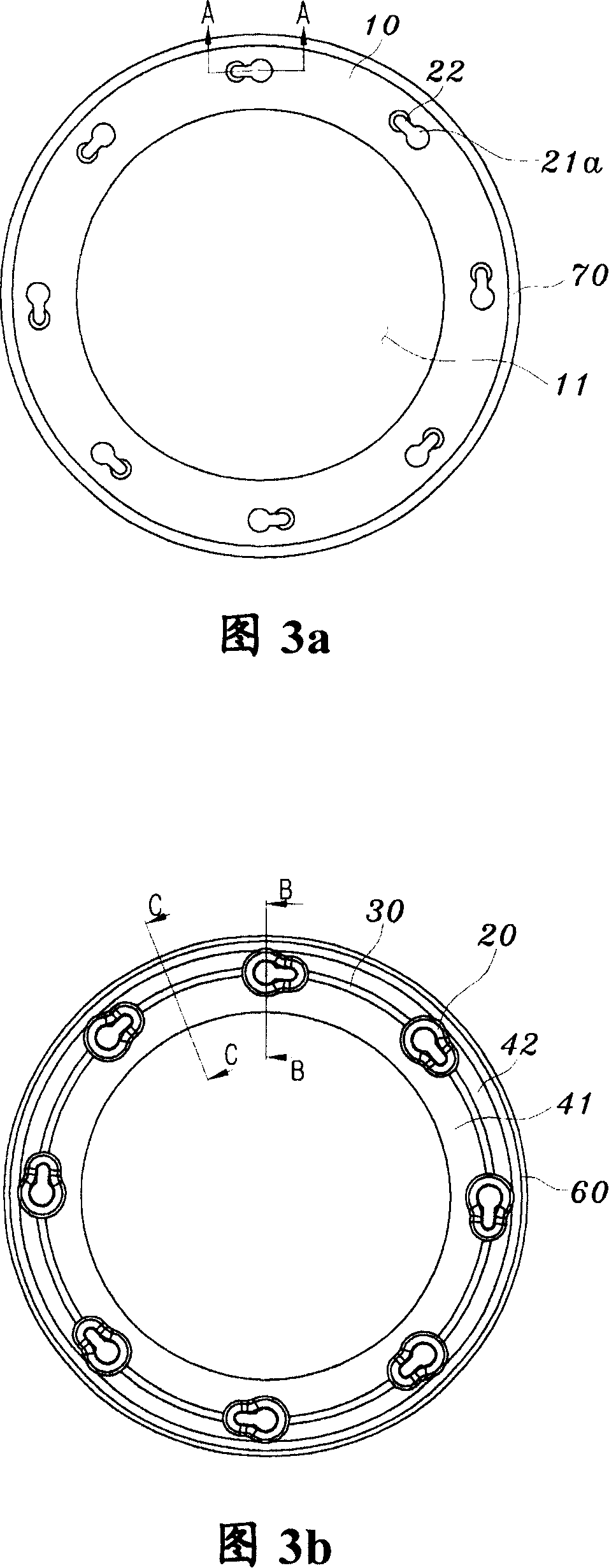
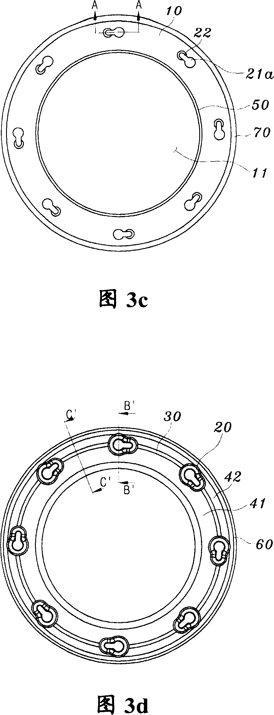
[0026] Fig. 3 a and Fig. 3 b are the two-sided structure diagrams of the flange concave structure used for the hollow concrete member according to the present invention, and Fig. 3 c and Fig. 3 d are the double-sided structure of the flange convex structure used for the hollow concrete member according to the present invention picture. Fig. 3a and Fig. 3c show the state diagram of the flange on the side not in contact with the concrete, an...


PUM


Abstract

The present invention relates to a flange used for hollow concrete pile and a fabrication method thereof. By using a casting method, a metal flange used for ground foundation engineering can be fabricated by a single work procedure to improve the production capacity; projecting par are projecting to reinforce the rigidity of an iron core and reinforcing steel; an inner groove and an outer groove are formed outside the projecting part, thereby saving the flange material and preventing the lost of manufacture cost and steel plate. For this purpose, the invention provides a flange which is formed with a hollow part at the center, and projects parts arranged in round shape and with certain thickness on one side, and iron core burying holes and reinforcing steel burying holes are formed in the projecting parts and are communicated with each other. The invention is characterized in that the projects parts on the flange are connected via rigid reinforcing strips, thereby the rigidity of the iron core and reinforcing steel arranged in the projecting part is strengthened.

Description

technical field [0001] The invention relates to a flange for a hollow concrete member integrally formed on both sides of a hollow concrete member and supporting an iron core buried inside the concrete member along the length direction and two ends of a steel bar. Background technique [0002] Generally, flange joints are used on both sides of concrete members. Concrete elements can be illustrated by, for example, concrete piles used in ground foundation works. [0003] An opening is formed at the center of the flange, and when the concrete pile is driven into the ground, soil on the ground can overflow through the opening. Figure 1 is a plan view of a traditional metal flange used in ground foundation engineering. Fig. 2 is a cross-sectional view taken along line V-V in Fig. 1 . [0004] Referring to Fig. 1 and Fig. 2, in the civil engineering carried out before the construction of the building, the concrete pile driven in order to strengthen the weak ground is formed by ...

Claims


Application Information

Patent Timeline
IPC IPC(8): E04B1/41B22D19/00
CPCE02D5/285E02D2300/0026
Inventor 金海权
Owner 金海权
Why Eureka
Try Eureka