Knitting method of tubular knitted fabric

A knitted fabric and tubular technology, which is applied in the knitting field of tubular knitted fabrics, can solve problems such as poor wearing feeling

Inactive Publication Date: 2008-04-02
SHIMA SEIKI MFG LTD
View PDF5 Cites 14 Cited by
  • Summary
  • Abstract
  • Description
  • Claims
  • Application Information

AI Technical Summary

Problems solved by technology

But even if only the finger pockets of the thumb are joined at the center of the palm of the four fingers, the position of the bases of the fingers joining eac...

Method used


Image

  • Knitting method of tubular knitted fabric
  • Knitting method of tubular knitted fabric
  • Knitting method of tubular knitted fabric

Examples


no. 1 approach

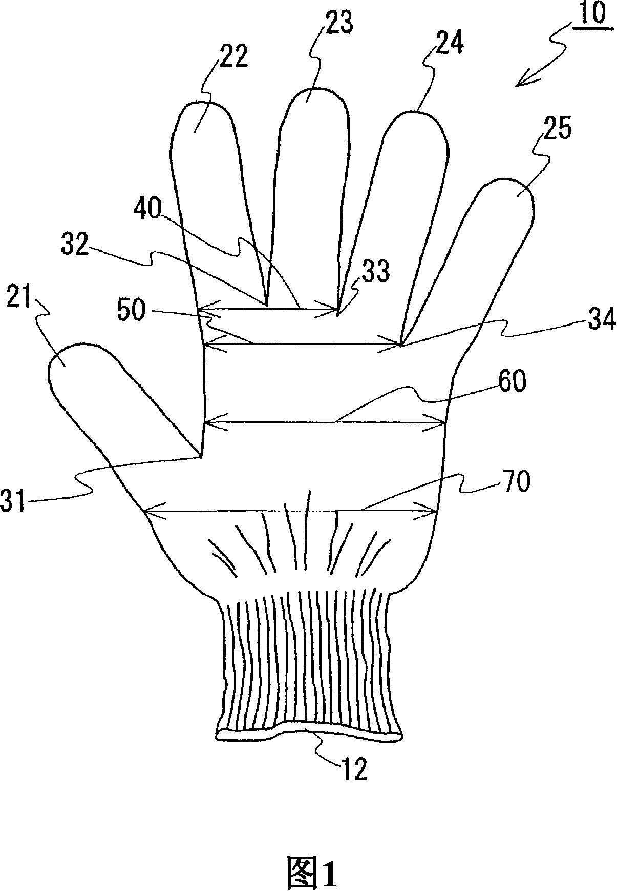
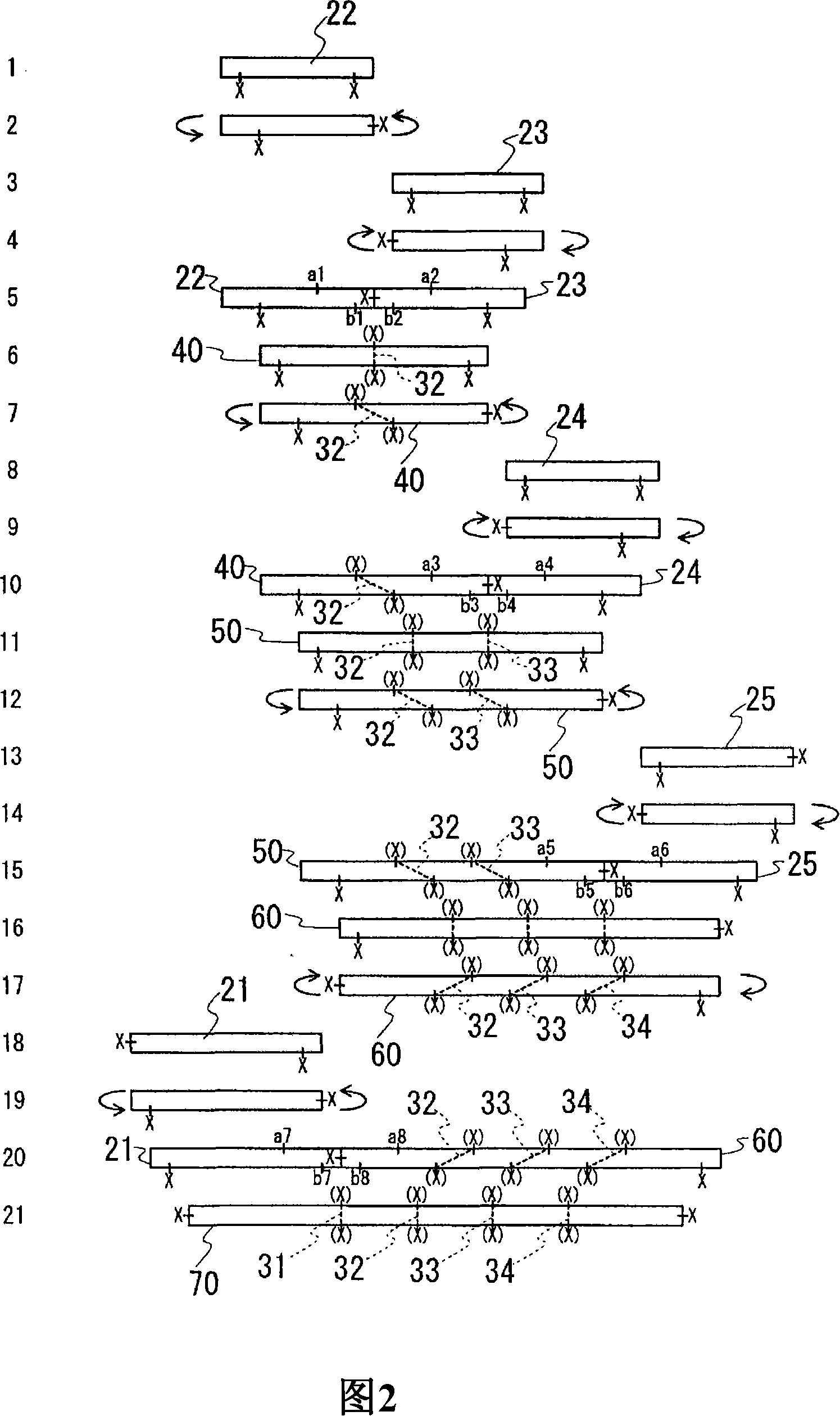
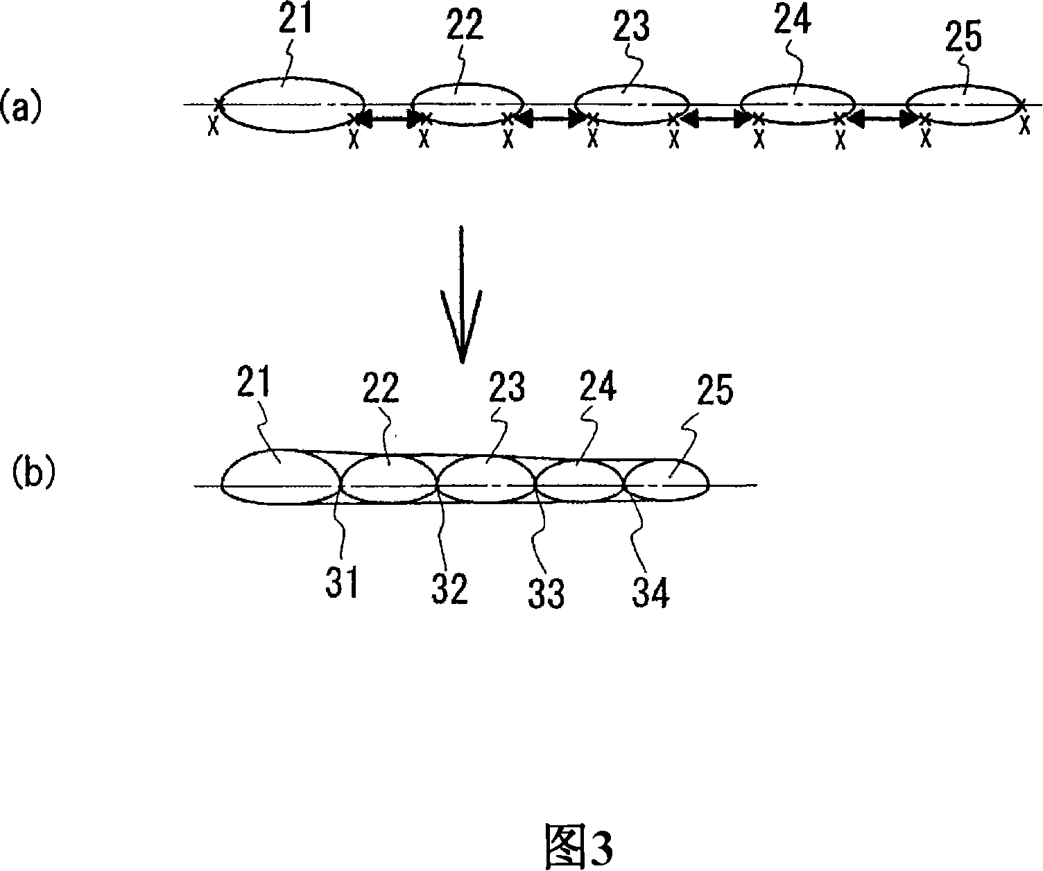
[0109] Fig. 1 is a plan view of a glove having five finger pockets according to a first embodiment. Fig. 2 is a knitting process diagram showing a method of knitting the glove shown in Fig. 1 . Fig. 3 is a cross-sectional view showing a state before and after joining of finger pockets. In the glove 10 of the present embodiment, as shown in FIG. 1 , the front end of the middle finger pocket 23 is the most protruding. Sequentially, the position of the tip of the fingertip is in a descending state.

[0110] And then, form the first root portion 31 between the thumb pocket portion 21 and the index finger pocket portion 22, form the second finger root portion 32 between the index finger pocket portion 22 and the middle finger pocket portion 23, and form the second finger root portion 32 between the ring finger pocket portion. The third finger base 33 is formed between the finger pockets 24 of the ring finger and the fourth finger base 34 is formed between the ring finger pocket 2...

no. 2 approach

[0146] A second embodiment will be described based on the knitting process diagram of FIG. 4 . The second embodiment is also a glove having five finger pockets, and the same components as those in the first embodiment are designated by the same reference numerals, and description thereof will be omitted.

[0147] The second embodiment differs from the first embodiment in that the thumb pocket portion 21 is longer in the knitting width direction of the front side knitted fabric (palm side knitted fabric) than in the knitting width direction of the rear side knitted fabric (back of hand side knitted fabric). The boundary portion X is set in such a manner that the index finger pocket portion 22 is set so that the length in the knitting width direction of the front side knitted fabric (palm side knitted fabric) is the same as the length in the knitting width direction of the rear side knitted fabric (the back side knitted fabric). Boundary X. The boundary portion X of the middle ...

no. 3 approach

[0161] The above-mentioned embodiments are embodiments of gloves, but the knitting method of the present invention can also be applied to the knitted pullover shown in FIG. 6 . In the third embodiment, a common double-bed flat knitting machine is used to knit a tubular body (tubular portion) and a tubular sleeve (tubular portion) independently, and join these body and sleeves to knit a knitted pullover. Condition.

[0162] FIG. 6 shows a plan view of the body and sleeves of the knitted pullover 100 viewed from the front body side. Fig. 7 is a knitting process diagram for knitting the above-mentioned knitted pullover 100 by the knitting method of the present invention, showing the knitting process when the body and sleeves are joined.

[0163] The knitted pullover 100 knitted in the third embodiment is a long-sleeved knitted pullover with a neckline, and has a front body 2 a , a rear body 2 b , left sleeves 3 , and right sleeves 4 . As shown in FIG. 6 , the front body 2 a and...


PUM


Abstract

A knitting method provides an easy-to-wear knitted tubular knitted fabric which gives little stretching feeling and exhibits high fitness upon wearing by joining at least three tubular parts. The method of a tubular knitted fabric using a flat knitting machine having at least a pair of front and back needle beds extending in a transverse direction and disposed opposite to each other in a cross direction, at least either of which is racked in the transverse direction so that loops can be transferred between the front and back needle beds comprises an operation of joining two tubular parts at a boundary of front and back knitted fabrics to form a tubular part is repeated; wherein the boundary is set so that the front knitted fabric and the back knitted fabrics are different in length in a knitting width direction immediately before joining for at least one tubular part; the tubular part in which the front and back knitted fabrics are different in length in the knitting width direction and the boundary to be joined is not positioned between the front and back needle beds is rotated so that the boundary is positioned between the front and back needle beds; and two adjacent tubular parts having the boundaries opposed to each other between the needle beds are joined while holding the boundary in between after the rotation.

Description

technical field [0001] The present invention relates to a method for knitting a tubular knitted fabric, which is formed by knitting on a flat knitting machine and joining three or more independently knitted tubular parts, and has high suitability when worn. Background technique [0002] Examples of the tubular knitted fabric obtained by joining three or more independently knitted tubular portions include gloves having finger pockets, socks having finger pockets, and sweaters. When using a flat knitting machine to knit a knitted pullover, as shown in Patent Document 1, the body is stitched from the hem, the sleeves are stitched from the cuffs, and the tubular body (tube) and tube are joined at the armhole. Shaped sleeve (tubular part). [0003] For gloves and socks having finger pockets, when using a flat knitting machine, each finger pocket is usually stitched from the fingertip as a single cylindrical portion. Then, the finger pockets are joined at the base of the finger....

Claims


Application Information

Patent Timeline
IPC IPC(8): D04B7/34D04B1/28A41D19/00A41B11/00A41D1/04D04B1/24D04B7/32
CPCA41D2500/10D04B1/246A41D19/00A41D1/04D04B1/28D10B2403/0333D04B1/24D04B1/26D04B7/34
Inventor 冈本一良
Owner SHIMA SEIKI MFG LTD
Why Eureka
Try Eureka