
Eureka
For R&D, Eureka makes reading and utilizing patents & technical documents easy.
Eureka AIR
Designed for self-driven R&D workflows. Generate viable solutions, solve complex R&D challenges, empower your innovation with AI.

Eureka Materials
Designed for material experts only. Revolutionize your material R&D, from search, analyze, to developing new materials.

TechResearch
Generate reliable direction feasibility study reports for your R&D in just a few steps.

TechSeek
Discover and master advanced knowledge NOW. Basics, ideas, possibilities, all at once.

TechMind
As an expert in R&D Theories, TechMind can generates customized viable solutions instantly.

TechRisk
Analyze your overall solution with one click, know your potential R&D risks in advance.

TechMonitor
Get weekly tech updates, stay abreast of the latest tech innovations and key insights.
Electric motor
A fan cover and fan technology, applied in the direction of electrical components, electromechanical devices, electric components, etc., can solve the problems of poor cooling air flow effect, large geometric shape and unreasonable material accumulation, saving space and reducing Vibration and rigidity improvement effect
- Summary
- Abstract
- Description
- Claims
- Application Information
AI Technical Summary
Problems solved by technology
Method used
Image

Examples
Embodiment Construction
[0022] The present invention is now described in detail with the aid of the accompanying drawings:
[0023] 1 to 6 show the electric machine according to the invention in different views, and FIGS. 7 and 8 show the lower part of the associated terminal box in different views.
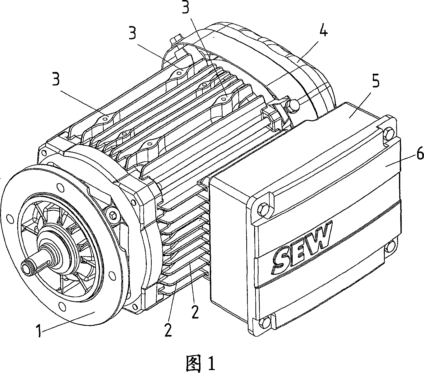
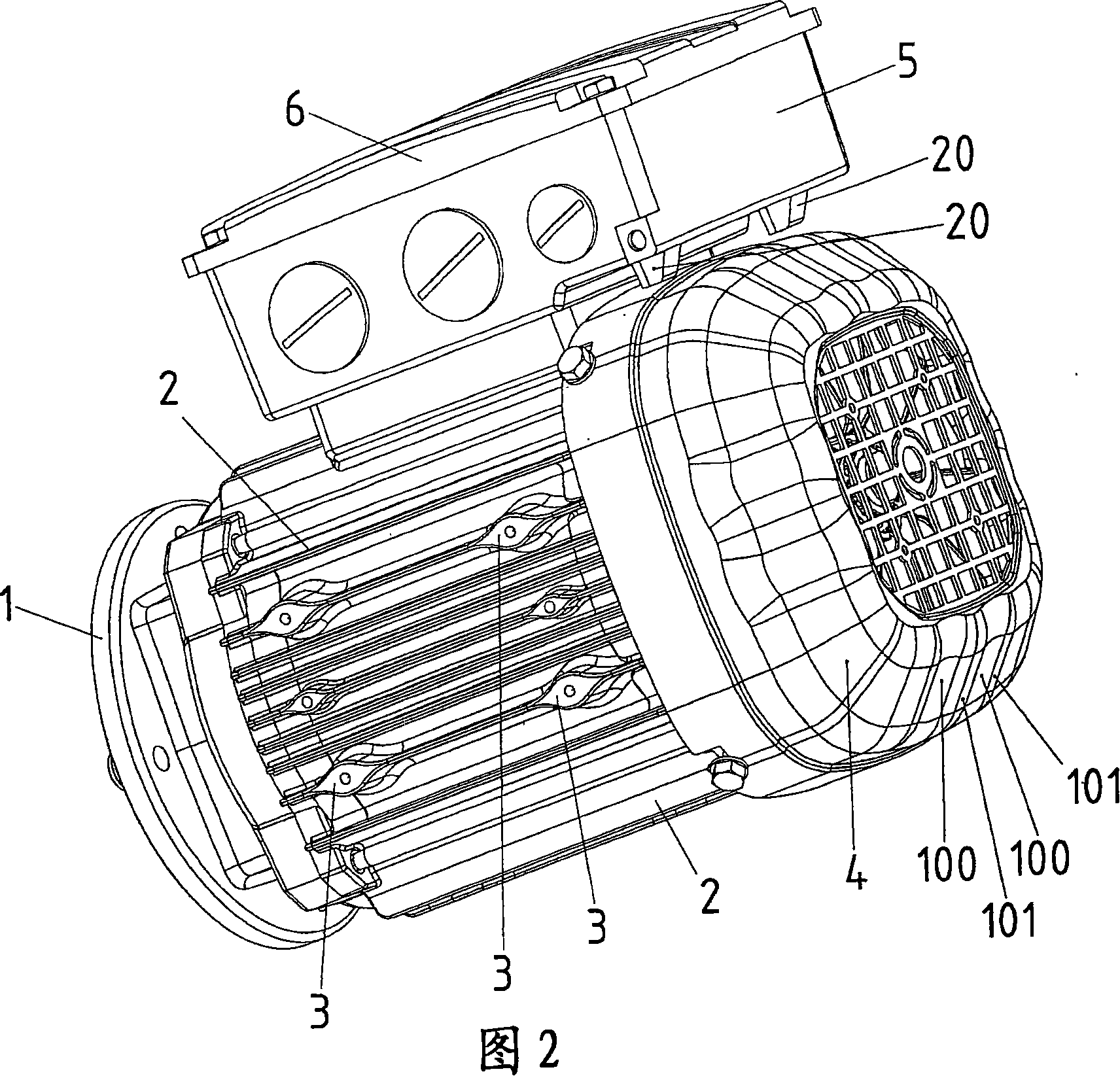
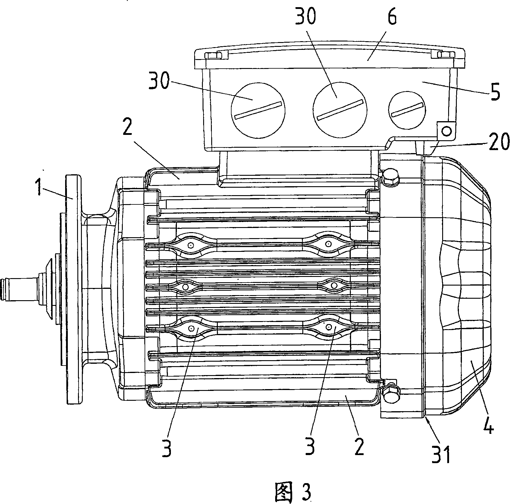
[0024] The motor is designed as an electric motor and has a flange 1 with which another device to be driven, such as a transmission or a stirrer, can be connected.
[0025] On its stator housing, the electric machine has cooling ribs 2 which partially have almond-shaped thickenings 3 . The fan guard 4 is arranged on the side opposite to the flange 1 . The terminal box, also called terminal box, consists of a terminal box lower part 5 and a terminal box upper part 6 detachably connected thereto as a cover. The terminal box bottom part 5 has, on its outer side facing the stator housing of the electric machine, a bead 20 which forms a material deposit for machining bores.
[0026] Since the parts of the...
PUM
 Abstract
Description
Claims
Application Information
 - R&D Engineer
- R&D Manager
- IP Professional
- Industry Leading Data Capabilities
- Powerful AI technology
- Patent DNA Extraction
Browse by: Latest US Patents, China's latest patents, Technical Efficacy Thesaurus, Application Domain, Technology Topic, Popular Technical Reports.
© 2024 PatSnap. All rights reserved.Legal|Privacy policy|Modern Slavery Act Transparency Statement|Sitemap|About US| Contact US: help@patsnap.com