Suspended ceiling structure for mobile house
A technology for prefabricated houses and suspended ceilings, applied in the direction of ceilings, building components, building structures, etc., can solve problems such as uneconomical, unbeautiful, unenvironmental protection, etc., and achieve the effect of easy disassembly
- Summary
- Abstract
- Description
- Claims
- Application Information
AI Technical Summary
Problems solved by technology
Method used
Image

Examples
Embodiment 1
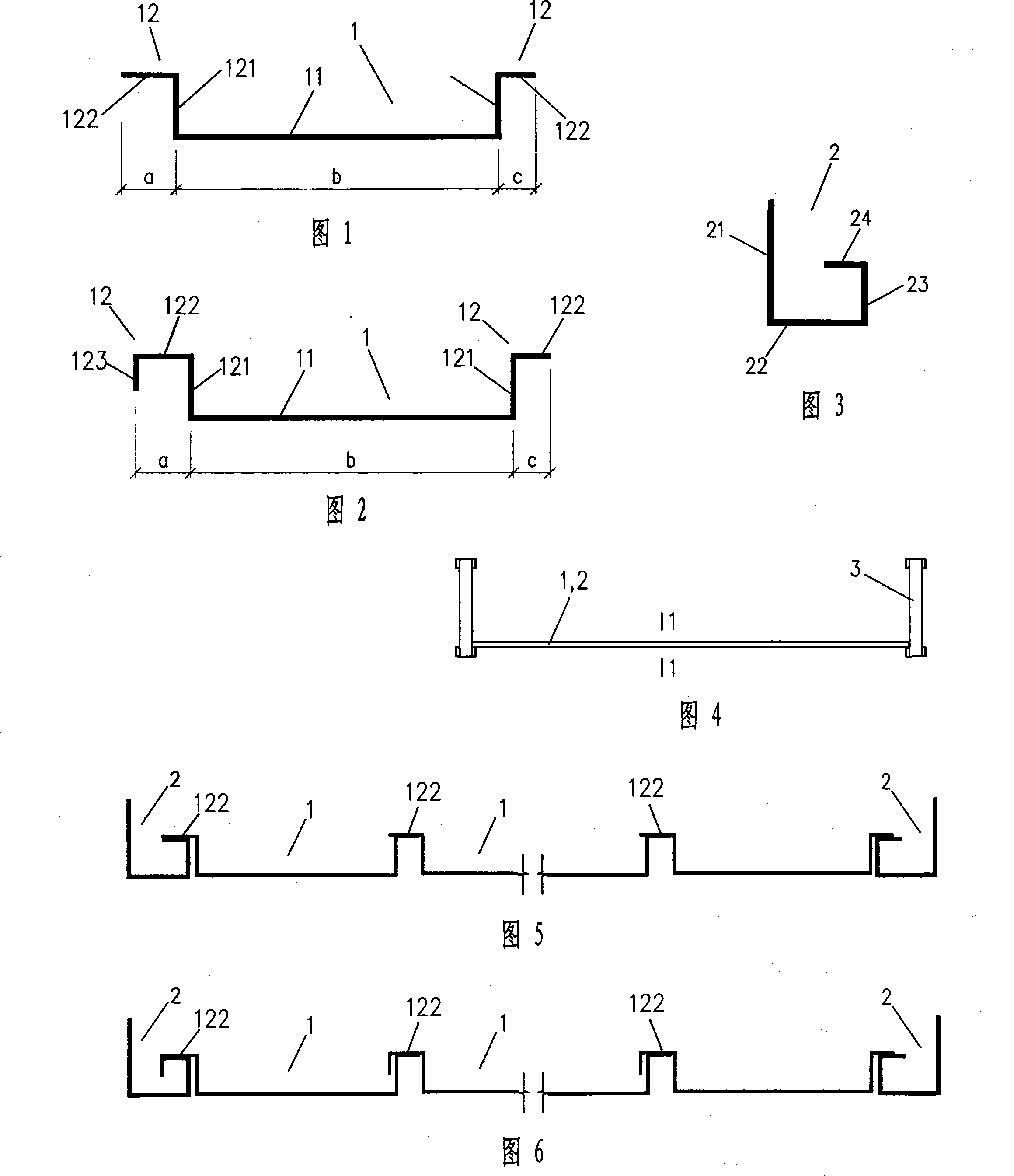
[0020] Embodiment 1: As shown in FIG. 1 , the ceiling batten 1 includes a horizontal panel 11 and connecting portions 12 extending upward from the left and right sides of the horizontal panel 11 . Each connecting portion 12 is in an inverted L shape and consists of a vertical plate surface 121 extending upward along the end of the horizontal panel 11 and a horizontal plate surface 122 extending horizontally outward along the top of the vertical plate surface 121 . Wherein, the heights of the vertical plate surfaces 121 of the connecting parts 12 on the left and right sides are the same to facilitate on-site installation and factory production, and the widths a and c of the horizontal plate surfaces 122 on both sides can be the same or slightly different. During installation, as shown in FIG. 5 , the adjacent ceiling battens 1 are spliced together by overlapping the adjacent horizontal board surfaces 122 .
Embodiment 2
[0021] Embodiment 2: As shown in FIG. 2 , the structure of the ceiling slat 1 is basically the same as that of the embodiment, and also includes a horizontal panel 11 and connecting parts 12 extending upward from the left and right sides of the horizontal panel 11 . The difference is that, The outer end of the transverse plate surface 122 of one side connecting portion 12 is also provided with a rib 123 extending vertically downwards to form an inverted U shape. The width a of the horizontal plate surface 122 on one side with the rib 123 is greater than or equal to the sum of the width c of the horizontal plate surface 122 on the other side and the thickness of the vertical plate surface 121, and the side with the rib 123 The riser surface 121 is slightly higher than the riser surface 121 on the other side, so that the connecting portion 12 of one side of a certain ceiling slat 1 with the rib 123 can be overlapped with the side of the adjacent ceiling slat 1 without the rib 123...
PUM
 Abstract
Description
Claims
Application Information
 - Generate Ideas
- Intellectual Property
- Life Sciences
- Materials
- Tech Scout
- Unparalleled Data Quality
- Higher Quality Content
- 60% Fewer Hallucinations
Browse by: Latest US Patents, China's latest patents, Technical Efficacy Thesaurus, Application Domain, Technology Topic, Popular Technical Reports.
© 2025 PatSnap. All rights reserved.Legal|Privacy policy|Modern Slavery Act Transparency Statement|Sitemap|About US| Contact US: help@patsnap.com