Device for removing water from a work-piece

A technology for workpieces and workpiece fixtures, which is applied in the field of devices for removing water from workpieces, and can solve problems such as insufficient water removal effects and high operating costs

Inactive Publication Date: 2008-04-09
SHIGAYAMASHITA
View PDF0 Cites 4 Cited by
  • Summary
  • Abstract
  • Description
  • Claims
  • Application Information

AI Technical Summary

Problems solved by technology

[0005] In addition, blowing compressed air requires a lot of energy, the water removal effect is not sufficient, and the operation cost is high

Method used


Image

  • Device for removing water from a work-piece
  • Device for removing water from a work-piece

Examples


Embodiment Construction

[0015] Hereinafter, the present invention will be described in detail with reference to the accompanying drawings.

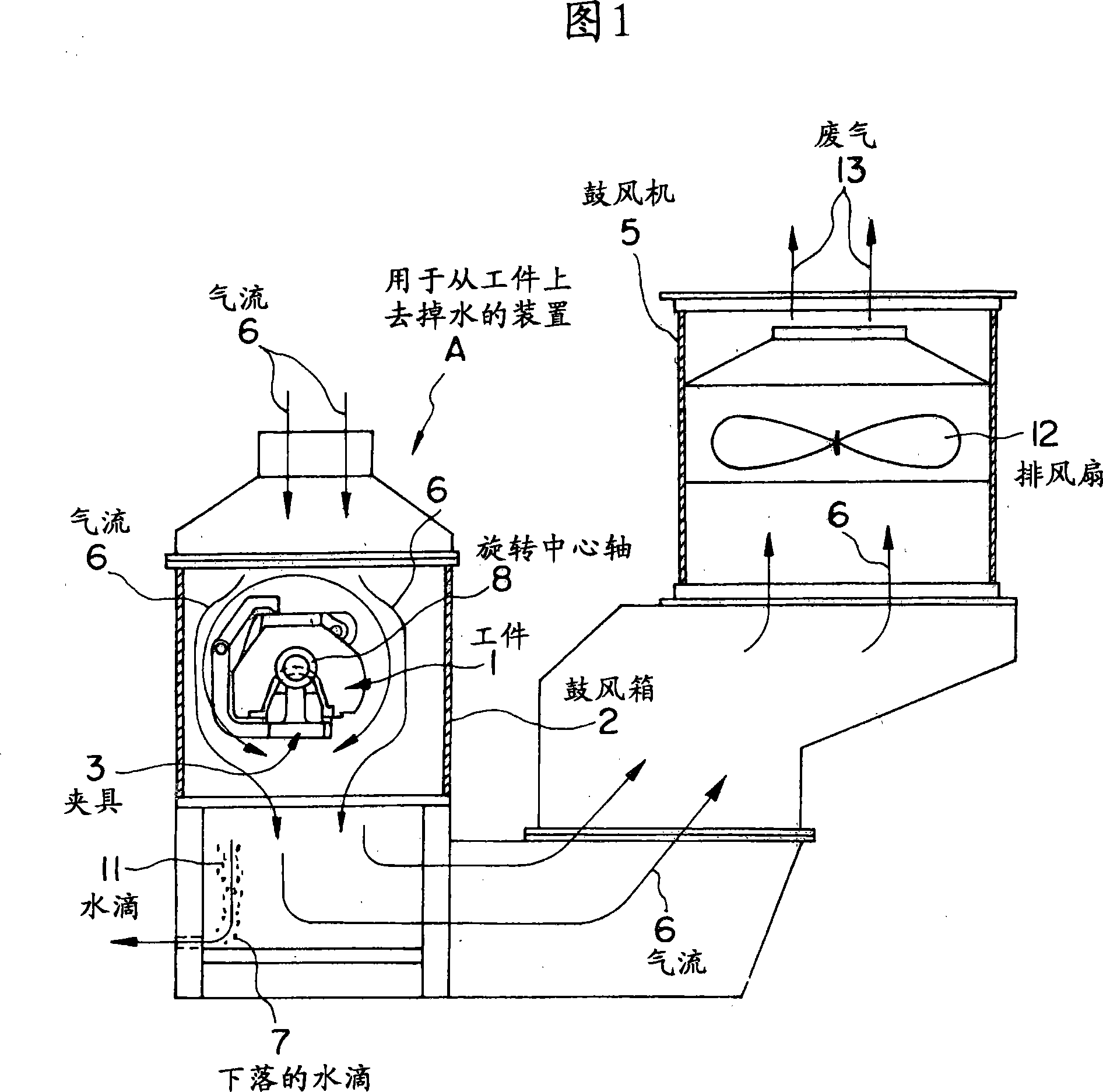
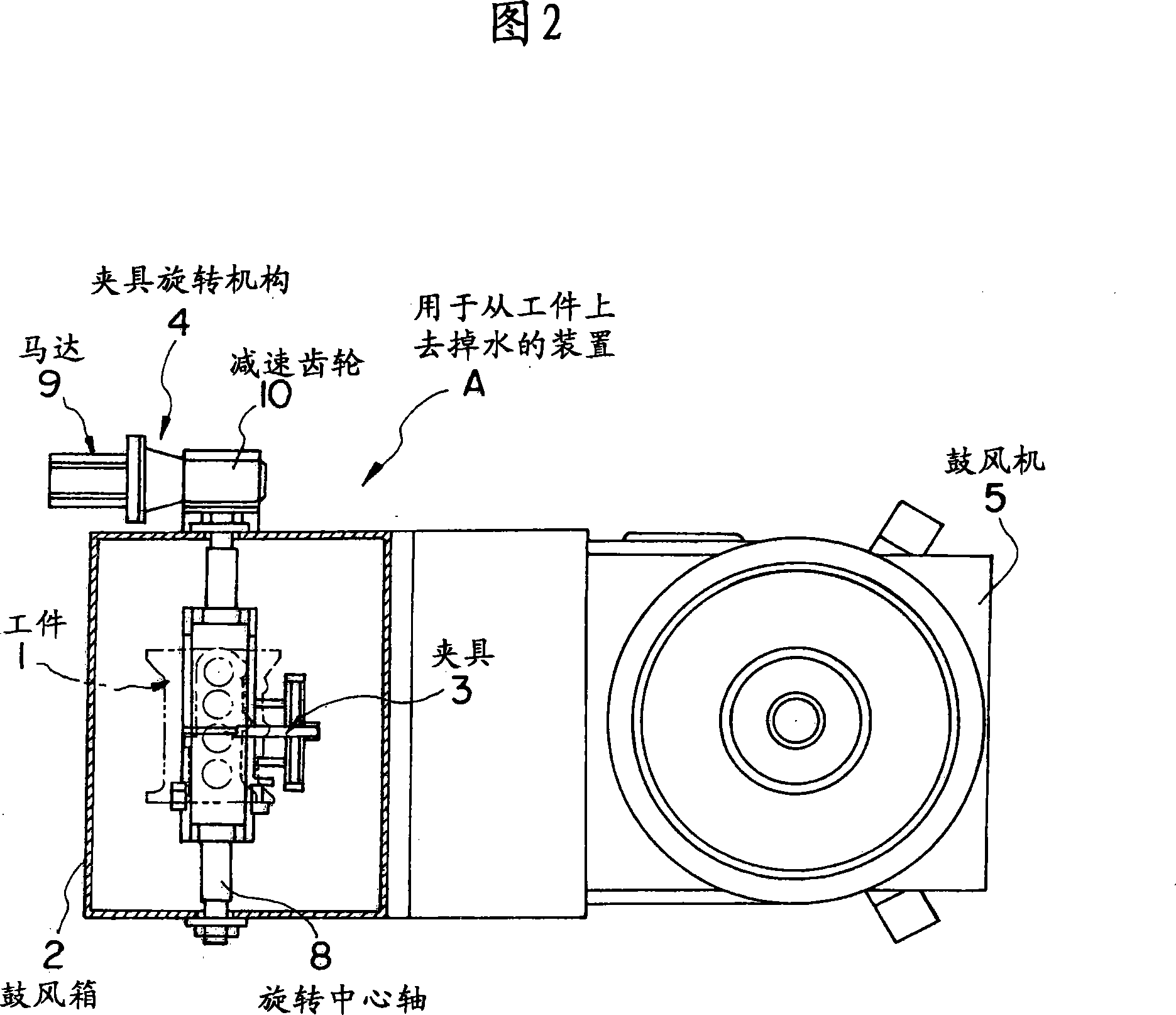
[0016] Fig. 1 is a side view of an embodiment of the present invention, and Fig. 2 is a plan view of the embodiment.

[0017] The present invention is a dewatering device A capable of completely (or sufficiently) removing residual liquid remaining on the surface or in a hole of a machined product (workpiece) 1 or the like. Blower box 2 , work clamp 3 , clamp rotation mechanism 4 and air blower 5 for workpieces subject to water are shown in FIG. 1 , which is a side view of dewatering device A . FIG. 2 is a plan view of the dewatering device A. FIG.

[0018] In the blower box 2, the workpiece 1 is set by a conveying device (not shown in the figure), the workpiece 1 is clamped, and then the inlet of the workpiece is closed with a baffle. The baffle is provided with openings for air entry.

[0019] The workpiece 1 clamped by the clamp 3 is rotated by the action o...


PUM


Abstract

The problem (object) is to provide a device for removing water from a machined piece (work) which realizes a technique for completely (sufficiently) removing water beads deposited on a work. [Means to Solve the Problem (Means to Attain the Object)] The water removing device comprises an air blowing box 2 for holding a work 1 to be subjected to water removal; a work clamping jig 3 mounted in the air blowing box 2 for clamping the work 1 ; a jig rotating mechanism 4 for rotating the work clamping jig 3 to rotate the clamped work 1 , thereby causing water beads deposited on the work 1 to drop; and an air blower 5 for generating an air current flowing in the same direction as the a falling direction of water drops 11 which have been caused to drop from the work 1.

Description

technical field [0001] The present invention relates to an apparatus for removing water from workpieces capable of removing water from the workpieces on which residual drops of water are deposited after cleaning machined products (workpieces) molded by casting (such as automobile parts, etc.) completely or substantially removed and discharged. Background technique [0002] Many different machine parts such as automotive parts are machined and then washed with water to remove deposited substances. [0003] As a technique for removing water from cleaned workpieces, hitherto, a technique has been employed that removes impurities on the surface of the workpiece or in holes or cavities by blowing compressed air onto the workpiece using a blower. residual liquid. [0004] However, in this blowing mode, there is a possibility that the blown fine water droplets are deposited on the workpiece again. Additionally, only water in the surface area of ​​the workpiece that is directly e...

Claims


Application Information

Patent Timeline
Patent Type & Authority Applications(China)
IPC IPC(8): F26B5/08F26B11/18
CPCB08B3/10B08B3/04B08B5/00F26B9/04F26B5/00
Inventor 市桥薰
Owner SHIGAYAMASHITA
Why Eureka
Try Eureka