
Enclosure assembly

A shell and component technology, applied in the direction of cabinet/cabinet/drawer parts, wing parts, door/window accessories, etc., can solve problems such as reducing hinge space

Inactive Publication Date: 2008-04-09
KONINKLIJKE PHILIPS ELECTRONICS NV
View PDF1 Cites 6 Cited by
  • Summary
  • Abstract
  • Description
  • Claims
  • Application Information

AI Technical Summary

Problems solved by technology

Although the hinge can be hidden or covered in the wall, this does not reduce the space occupied by the hinge

Method used


Image

  • Enclosure assembly

Examples


Embodiment Construction

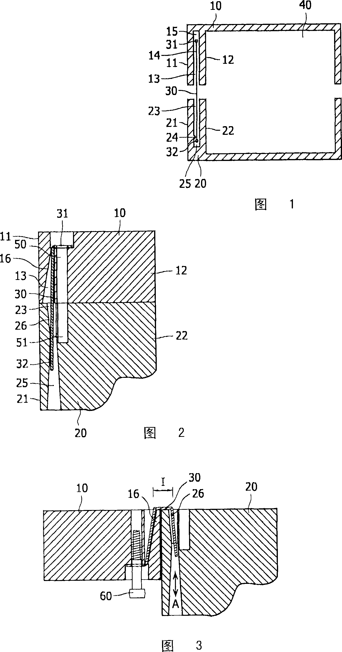
[0026] Fig. 1 schematically shows a cross-section of a housing assembly according to the invention.

[0027] In the figure, 10 denotes a first housing part. The first housing part 10 has a first outer surface 11 and a first inner surface 12 and a first groove 13, and the first groove 13 has a first element fixing device 14.

[0028] In the figure, 20 denotes a second housing part. The second housing part 20 has a second outer surface 21 and a second inner surface 22 and a second groove 23, and the second groove 23 has a second element fixing device 24.

[0029] The hinge element 30 includes a first snap lock device 31 and a second snap lock device 32. Reference numerals 15 and 25 denote first and second sliding spaces.

[0030] The internal space 40 is closed by the housing assembly in the closed position.

[0031] As shown in Fig. 1, the housing assembly is basically symmetrical, but this is not necessary in the case of an actual embodiment. Moreover, the walls of the housing par...


PUM


Abstract

The invention provides a hingeably closeable enclosure assembly, wherein at least two enclosure parts (10, 20) are connected by a hinge element (30), which is accommodated in a recess (13, 23). The hinge element (30) is flexible, and preferably ribbon- shaped, and is slideably moveable in the recess. This configuration allows the hinge to be invisible from the outset, and to occupy the least amount of space.

Description

Technical field [0001] The present invention relates to a housing assembly, in particular to a housing assembly for enclosing an electronic device according to the preamble of claim 1. [0002] Such a housing assembly provides a closed space in which electronic devices or similar devices can be enclosed. This kind of housing has an outer wall which is substantially free of protrusions, especially no external hinges. Background technique [0003] Known housing components with hinges that are not visible from the outside are, for example, automobiles or furniture with doors. For design or safety reasons, door hinges are often inside. For example, US 6,487,755 discloses a hidden hinge for furniture doors. [0004] The problem with the known assembly is that the hinge occupies a relatively large space. This is caused by the hinge that extends into the enclosed space. Although the hinge can be hidden or covered in the wall, this does not reduce the space occupied by the hinge. Especia...

Claims


Application Information

Patent Timeline
Patent Type & Authority Applications(China)
IPC IPC(8): E05D1/02H05K5/02
CPCE05D3/022E05D1/02E05Y2900/208E05Y2999/00
Inventor N·A·范里斯维克
Owner KONINKLIJKE PHILIPS ELECTRONICS NV
Learn More