Cross-quad and vertically coupled inertial sensors

一种惯性传感器、传感器元件的技术,应用在传感器领域,能够解决陀螺仪错误输出、不均衡、错误读数等问题

Active Publication Date: 2008-04-09
ANALOG DEVICES INC
View PDF3 Cites 10 Cited by
  • Summary
  • Abstract
  • Description
  • Claims
  • Application Information

AI Technical Summary

Problems solved by technology

In particular, MEMS gyroscopes can produce erroneous readings if they are not able to distinguish rotational vibration from the actual motion they are intended to detect
[0003] Additionally, deformation of the geometry of a MEMS device with a vibrating mass, such as a gyroscope, can create an imbalance in forces transverse to the longitudinal drive fingers
This imbalance results in a net force that is indistinguishable from the Coriolis force
Therefore, the gyroscope may produce erroneous output

Method used


Image

  • Cross-quad and vertically coupled inertial sensors
  • Cross-quad and vertically coupled inertial sensors
  • Cross-quad and vertically coupled inertial sensors

Examples


Embodiment Construction

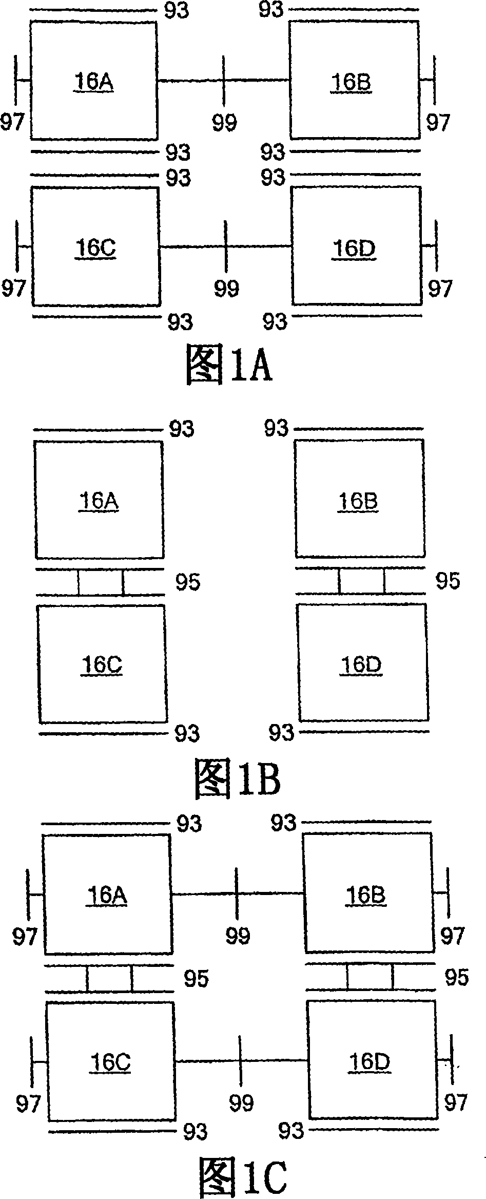
[0041] In a particular embodiment of the invention, the inertial sensor comprises four sensor elements arranged in a "cross quad" configuration. In a preferred embodiment, these sensor elements are microelectromechanical system (ie, "MEMS") gyroscopes. The sensor elements are combined to effectively perform the functions of a single gyroscope. The sensor elements are typically suspended above one or more lower substrates (not shown), and secured to the substrate (or substrates) at various points. The desire for gyroscopes using interleaved quad structures is discussed in US Patent 6,122,961, the disclosure of which is incorporated herein by reference in its entirety.

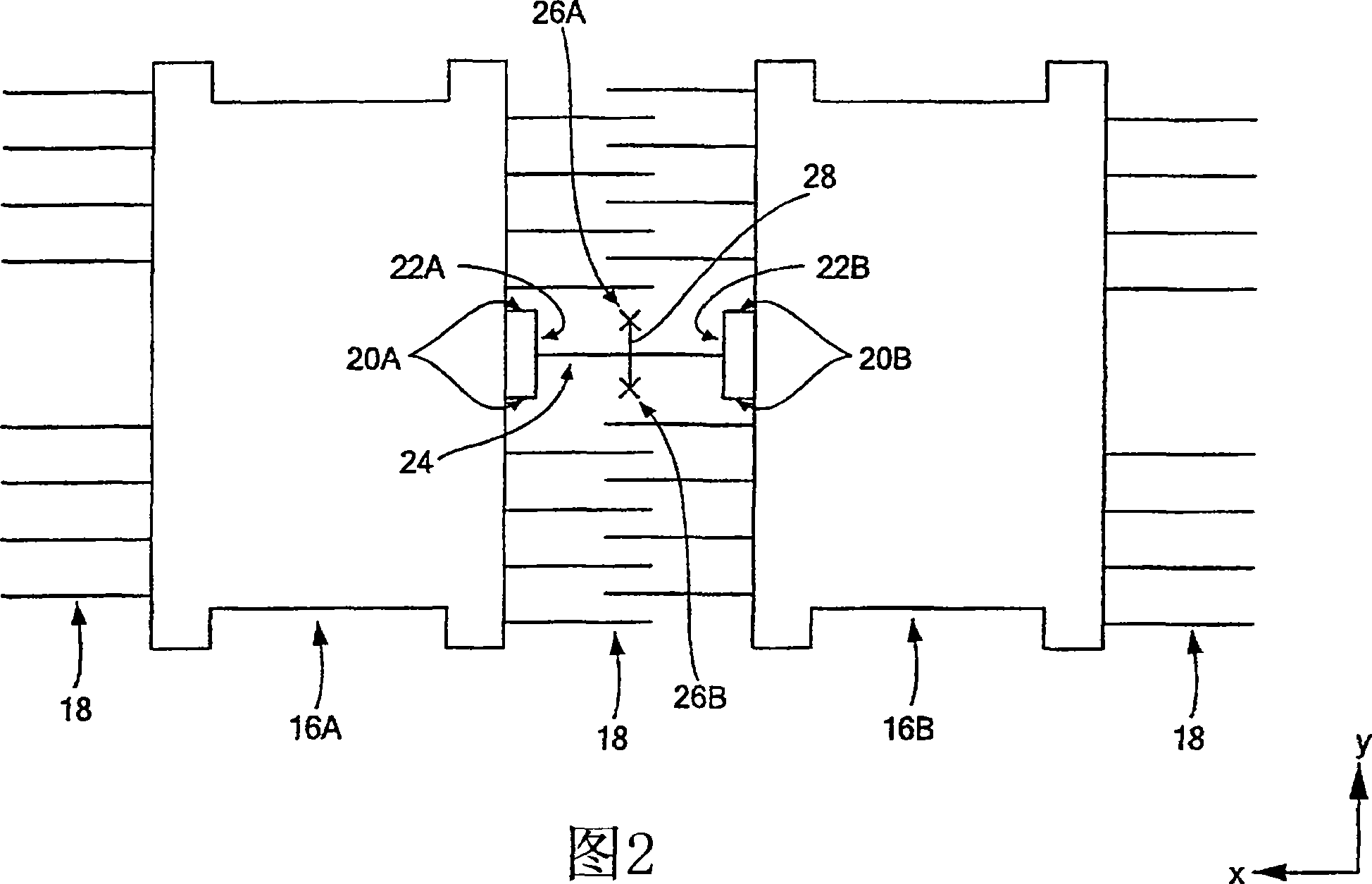
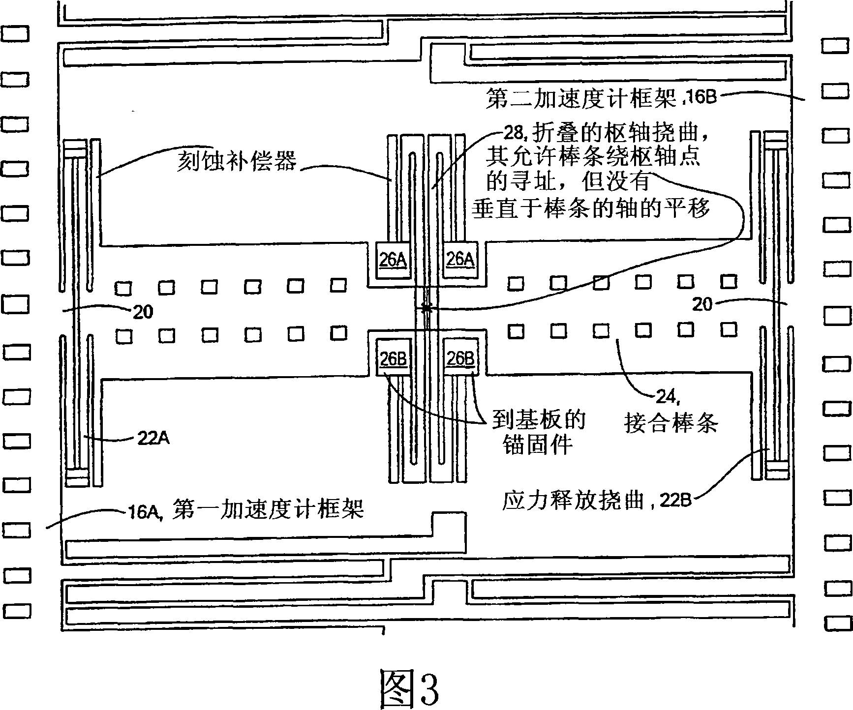
[0042] Each gyroscope has at least one resonator (mass) suspended within a frame. For purposes of discussion, the resonator of the inertial sensor is configured to move along two parallel X-axes, while the frame of the inertial sensor is configured to move along two parallel Y-axes perpendicular to the X-axis....


PUM


Abstract

An inertial sensor includes a cross-quad configuration of four interconnected sensor elements. Each sensor element has a frame and a resonator suspended within the frame. The sensor elements are arranged so that the frames of adjacent sensor elements are allowed to move in anti-phase to one another but are substantially prevented from moving in phase with one another. The sensor elements may be configured in a horizontally coupled arrangement, a vertically coupled arrangement, or a fully coupled arrangement. A pair of sensor elements may be vertically coupled.

Description

technical field [0001] The present invention relates generally to sensors, and more particularly, the present invention relates to inertial sensors. Background technique [0002] Inertial sensors, such as MEMS gyroscopes, are often adversely affected by rotational vibration noise (often referred to as "runout") at the drive frequency. In particular, MEMS gyroscopes can produce erroneous readings if they are not able to distinguish rotational vibration from the actual motion they are intended to detect. [0003] In addition, deformation of the geometry of a MEMS device with a vibrating mass, such as a gyroscope, can create an imbalance in forces transverse to the longitudinal drive fingers. This imbalance results in a net force that is indistinguishable from a Coriolis force. Therefore, the gyroscope may produce erroneous output. There are at least two sources of these geometric distortions. One originates from surface shearing of the substrate (eg, from release / wafer bow...

Claims


Application Information

Patent Timeline
Patent Type & Authority Applications(China)
IPC IPC(8): G01C19/56
CPCG01C19/574G01C19/5719G01C19/56
Inventor 约翰·A·吉恩邝锦波
Owner ANALOG DEVICES INC
Why Eureka
Try Eureka