Quick coupling with volume displacement passage

a technology of volume displacement and coupling, which is applied in the direction of couplings, sealing/packing, and wellbore/well accessories, etc., can solve the problems of affecting the sealing of the piston and/or the piston itself, and affecting the sealing surface of the chamber behind the piston

Active Publication Date: 2019-05-16
PARKER INTANGIBLES LLC
View PDF35 Cites 9 Cited by
  • Summary
  • Abstract
  • Description
  • Claims
  • Application Information

AI Technical Summary

Benefits of technology

[0006]It is desirable that a dummy coupling does not ingress seawater, and also that the dummy coupling constrains pressure should the valve in the standard coupling ever leak while being connected to the dummy coupling. The quick

Problems solved by technology

If as referenced above the piston of the conventional configuration does not move during the first connection topside, and the coupling is then placed subsea, the sealing surface of the chamber behind the piston could be damaged due to marine growth and calciferous deposits.
If the coupling is then disconnected and

Method used


Image

  • Quick coupling with volume displacement passage
  • Quick coupling with volume displacement passage
  • Quick coupling with volume displacement passage

Examples


Embodiment Construction

[0020]Embodiments of the present invention will now be described with reference to the drawings, wherein like reference numerals are used to refer to like elements throughout. It will be understood that the figures are not necessarily to scale.

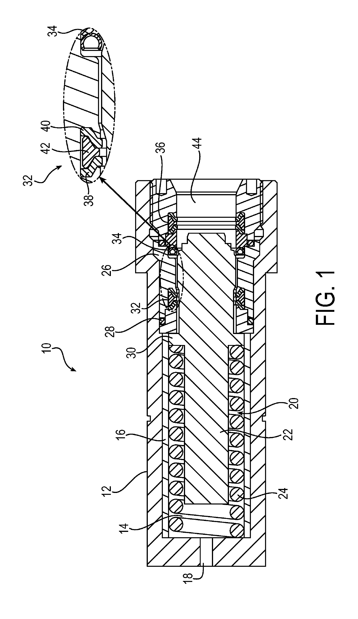
[0021]FIG. 1 is a drawing depicting an exemplary first coupling element 10 that may constitute a component of a coupling assembly in accordance with embodiments of the present invention. The first coupling element 10 may be configured as a cap element portion that acts as a dummy coupling element as referenced above. The first coupling element 10 may include a coupling body 12 that acts as an outer housing and defines a bore 14. Optionally, the bore 14 may be lined with a bore liner 16 that prevents any wear on the inner surface of the coupling body 12. The coupling body 12 further may define a vent passage 18 that is configured as part of a volume displacement passage for the venting of seawater and other contaminants from the coupling assemb...


PUM


Abstract

A quick coupling assembly includes a first coupling element (10) and a second coupling element (50) that is inserted into the first coupling element. The first coupling element has a coupling body (12) and a valve (20), which define a volume displacement passage. When the second coupling element (50) is inserted, the second coupling element mechanically acts on the valve (20) to expel contaminants from the quick coupling assembly via the volume displacement passage. The valve includes a poppet (22) and a biasing spring (24), and the volume displacement passage includes a leak path (66) defined between the coupling body and the poppet. The poppet has an inward contour (68) that is spaced apart from the coupling body to define the leak path. The poppet has a widened portion (70) that provides a sealing surface when the assembly is fully coupled. The second coupling element (50) mechanically acts on the poppet (22) during insertion to expel the contaminants via the volume displacement passage.

Description

FIELD OF INVENTION[0001]The present invention relates generally to quick couplings, and more particularly to multi-couplings for connecting multiple fluid lines in high pressure systems.BACKGROUND OF THE INVENTION[0002]Quick couplings in general are common devices for coupling fluid lines, without the need for special tools. Quick couplings, for example, may be configured as individual couplings for the connection of a single fluid line. Individual quick couplings typically have a ball locking mechanism to hold two halves of the coupling together as they try to separate from internal pressures. Alternatively, a quick coupling may be configured as a multi-coupling for connecting any number of multiple fluid lines. The multi-coupling constitutes a group of quick couplings mounted together in a plate or casting. In place of an individual locking mechanism for each individual coupling, a multi-coupling typically has a larger centralized locking mechanism that connects and holds the grou...

Claims


Application Information

Patent Timeline
IPC IPC(8): F16L57/00E21B33/038
CPCF16L57/005E21B33/038F16L55/115E21B17/02F16L37/33Y10T137/87957
Inventor NICK, LEONARDMARQUIS, TIMOTHYLEMAY, PAULKOLLER, JASON
Owner PARKER INTANGIBLES LLC
Why Eureka
Try Eureka