Heat treatment apparatus

A technology of heat treatment device and treatment container, which is applied in lighting and heating equipment, gaseous chemical plating, coating and other directions, can solve the problems of metal contamination of wafers, crack particles in furnace mouth 2a, etc., to prevent metal contamination, prevent cracks and other damages , the effect of improving durability

Active Publication Date: 2008-04-16
TOKYO ELECTRON LTD
View PDF1 Cites 5 Cited by
  • Summary
  • Abstract
  • Description
  • Claims
  • Application Information

AI Technical Summary

Problems solved by technology

[0005] However, in the former heat treatment apparatus, there is a problem that, when the inside of the processing container 3 is in a depressurized state, the gap between the lid body 15 and the furnace mouth 2a (specifically, between the furnace mouth flange 3a ) Because the above-mentioned O-ring 32 is crushed, the cover body 15 is in direct contact with the furnace mouth 2a (specifically the furnace mouth flange 3a), so that the active force acts on the furnace mouth 2a (specifically the furnace mouth flange 3a) , resulting in the generation of cracks on

Method used


Image

  • Heat treatment apparatus
  • Heat treatment apparatus
  • Heat treatment apparatus

Examples


Embodiment Construction

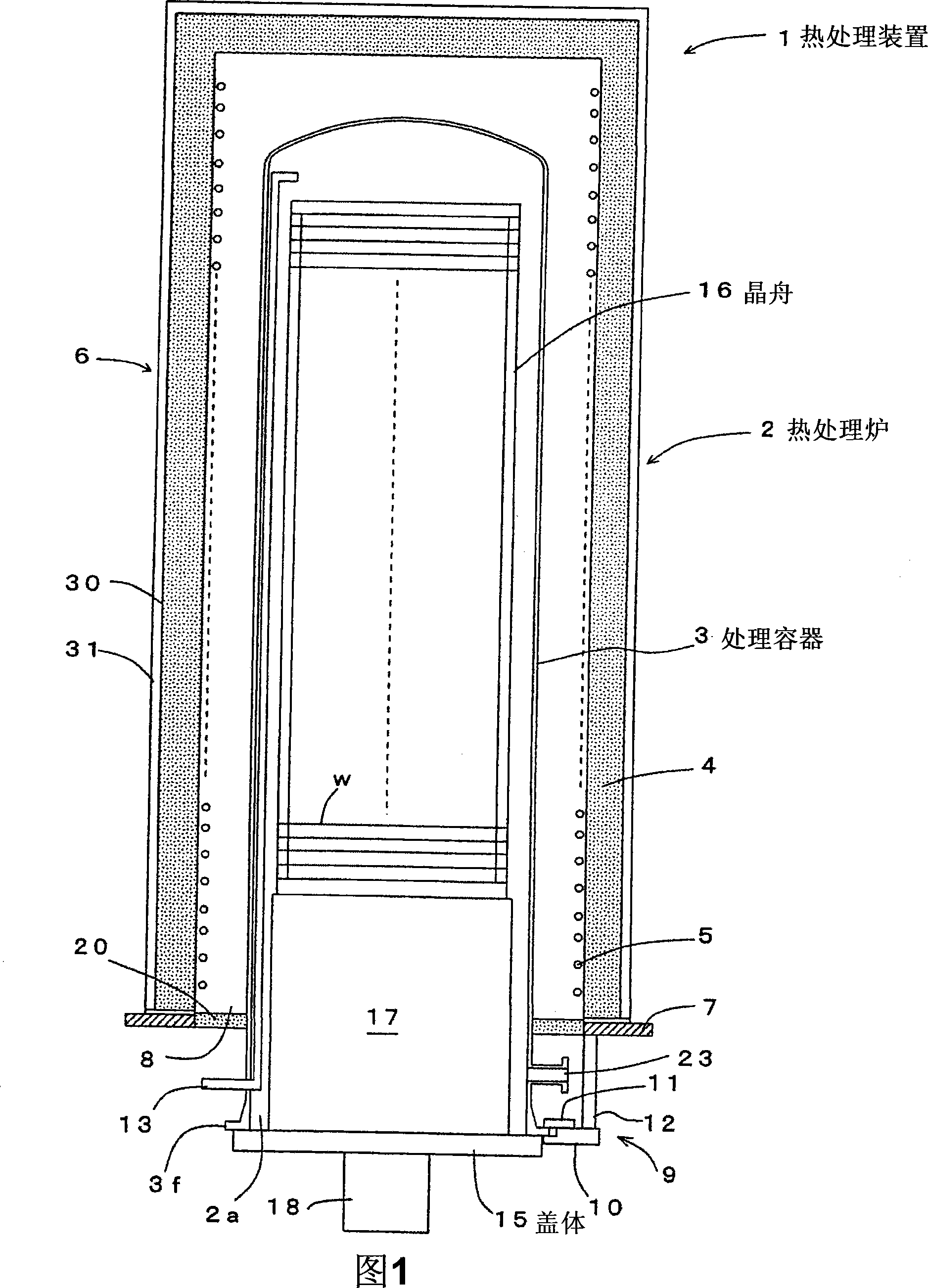
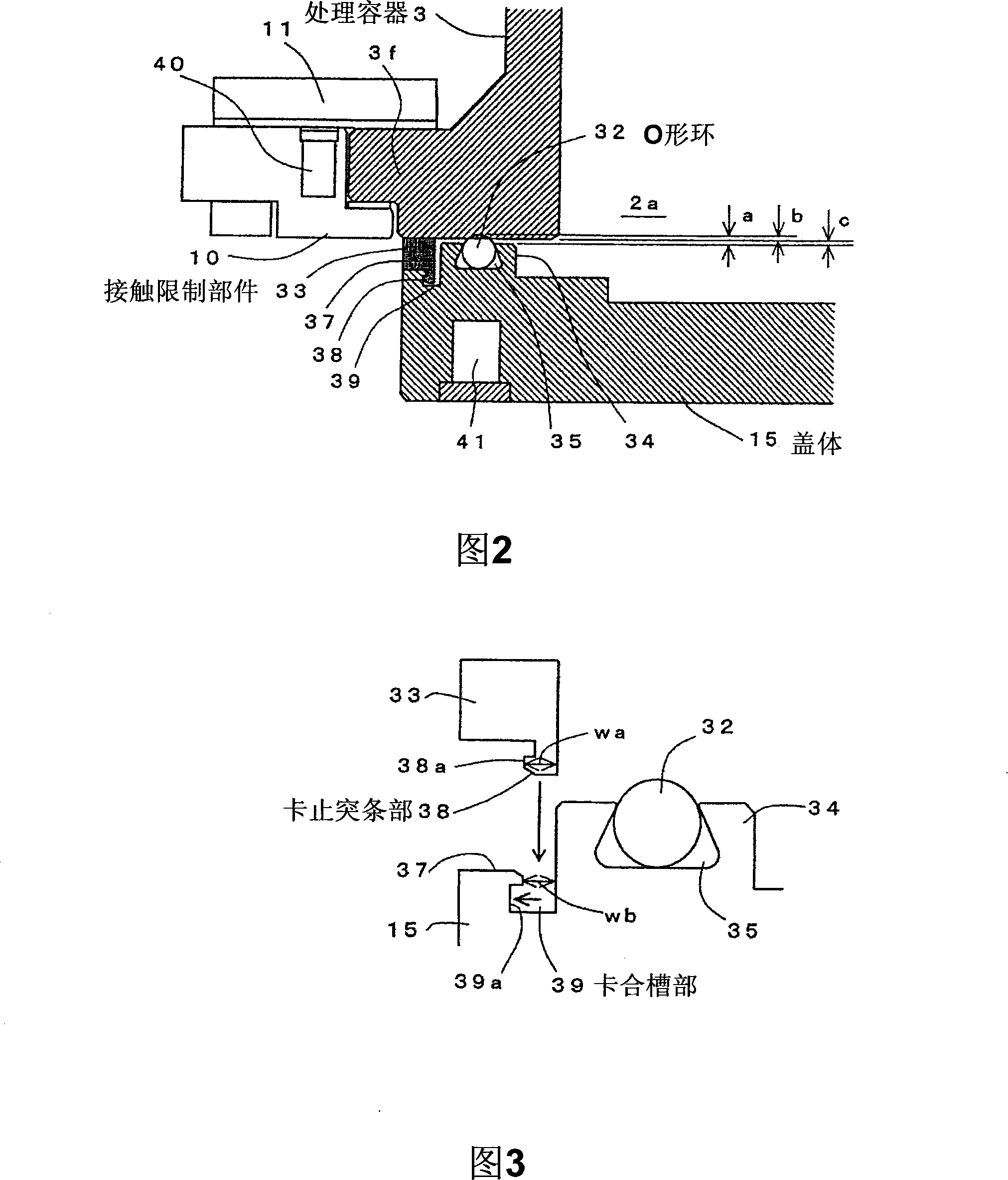
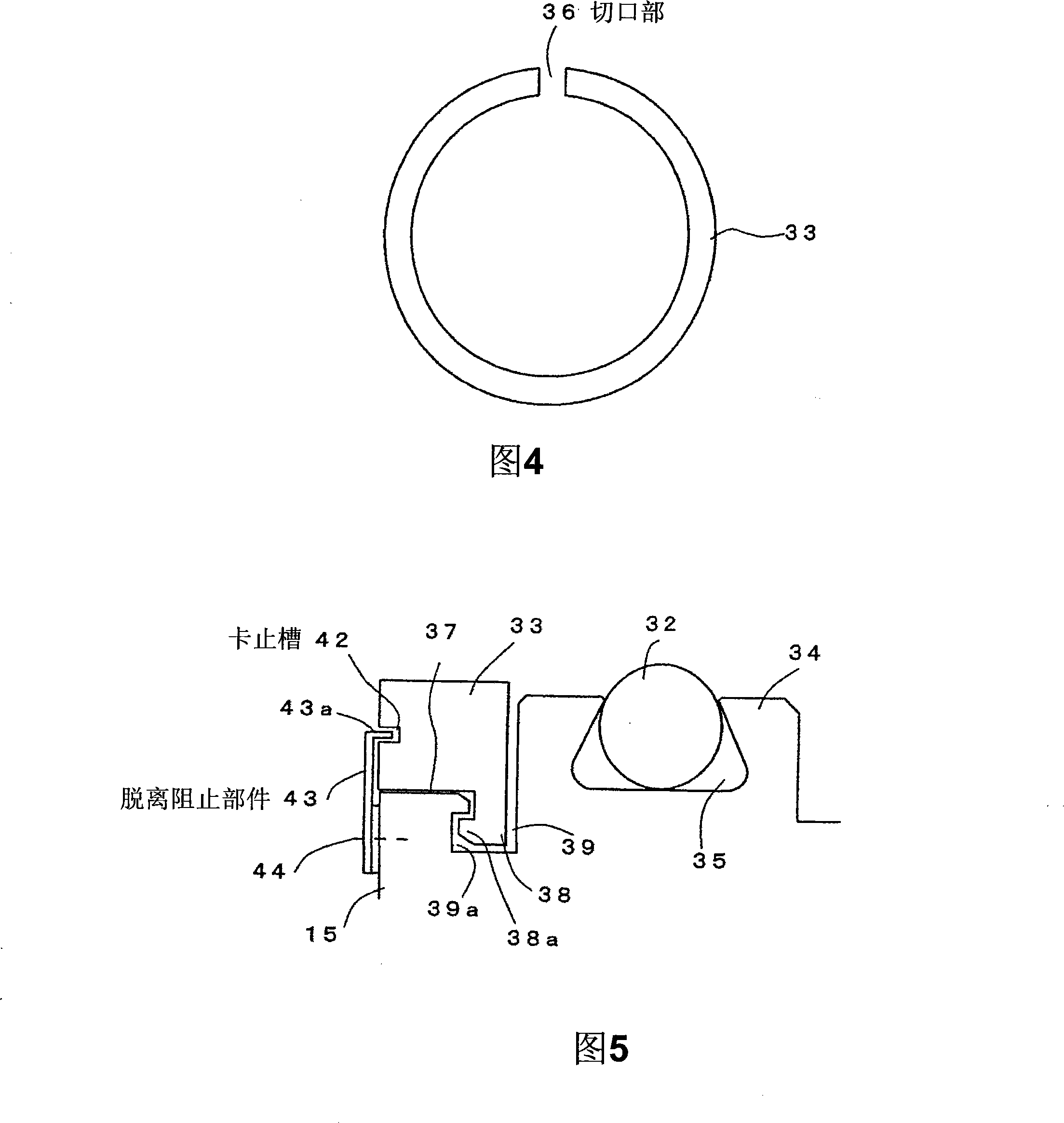
[0031] Hereinafter, the best mode for carrying out the present invention will be described in detail with reference to the drawings. 1 is a longitudinal sectional view schematically showing a heat treatment apparatus according to a first embodiment of the present invention, FIG. 2 is an enlarged sectional view of main parts of the heat treatment apparatus, and FIG. 3 is an explanatory diagram illustrating a structure for attaching a contact limiting member to a cover, Fig. 4 is a perspective view of a contact limiting member.

[0032] In Fig. 1, what numeral 1 represents is a vertical heat treatment apparatus as one of semiconductor manufacturing apparatuses, and this heat treatment apparatus 1 has the capability of accommodating a plurality of objects to be processed (such as wafers W) at a time and capable of decompressing the objects to be processed. Vertical heat treatment furnace 2 for heat treatment such as diffusion. This heat treatment furnace 2 mainly includes: a pro...


PUM


Abstract

Disclosed is a heat treatment apparatus which includes a processing vessel having a furnace throat at its bottom and adapted to accommodate process objects therein to perform a heat treatment to the process objects under reduced pressure, the processing vessel having a vessel main body made of quartz, a metallic lid adapted to support thereon a holder for holding a plurality of process objects so as to load and unload the holder into and from the processing vessel and to close and open the furnace throat, and an annular sealing member disposed on the lid to seal a gap between the lid and the furnace throat. A contact-preventing member is disposed between the lid and the furnace throat to prevent contact of the lid with the furnace throat due to squashing of the sealing member that would otherwise occur when an internal pressure of the processing vessel is reduced.

Description

technical field [0001] The present invention relates to heat treatment apparatus. Background technique [0002] In the manufacture of semiconductor devices, various processing devices (semiconductor manufacturing devices) are used in order to perform oxidation, diffusion, CVD (Chemical Vapor Deposition: Chemical Vapor Deposition) on objects to be processed such as semiconductor wafers (hereinafter referred to as wafers). . Among them, as one type of processing apparatus, there is known a batch-type heat processing apparatus capable of heat-treating a plurality of objects at one time, such as a vertical heat processing apparatus (for example, refer to Japanese Patent Application Laid-Open No. 2001-237238). [0003] As partially shown in FIG. 13, as the heat treatment device, there is the following device (for example, a decompression diffusion device, hereinafter referred to as the former heat treatment device), which includes a quartz processing container (processing tube: ...

Claims


Application Information

Patent Timeline
IPC IPC(8): H01L21/00H01L21/02H01L21/22H01L21/205H01L21/31H01L21/324H01L21/67C23C16/00F27B17/00
Inventor 高桥喜一佐瀬雄一郎佐藤泉高桥清彦
Owner TOKYO ELECTRON LTD
Why Eureka
Try Eureka