Converter with continuously adjustable output

A converter and output technology, applied in the field of improvement of voltage converter circuits, can solve the problems of increasing the steps of the driving circuit, cost and complexity, limitation of the maximum duty cycle of the circuit, electromagnetic interference, etc. Immediate simplicity of stability, reduction in size and cost

Active Publication Date: 2011-10-26
SHENZHEN MINDRAY BIO MEDICAL ELECTRONICS CO LTD +1
View PDF3 Cites 0 Cited by
  • Summary
  • Abstract
  • Description
  • Claims
  • Application Information

AI Technical Summary

Problems solved by technology

However, the BUCK-BOOST converter has the following disadvantages: 1) Compared with the BUCK or BOOST converter, the BUCK-BOOST can achieve a larger output voltage range, but its input current is intermittent and pulsating , which is not allowed in the ultrasonic power supply system, especially the high-frequency AC component of the input current will produce serious electromagnetic interference and affect the quality of ultrasonic images
Although it is possible to add a low-pass filter to the input end, it will increase the circuit volume and increase the cost
2) The drive circuit is complex
There are two switching tubes Q1 and Q2 in the circuit. Q1 needs to be driven by high side, and Q2 is driven by low side. It is usually realized by gate drive transformer, which increases the steps, cost and complexity of the drive circuit. More importantly, , since the driving transformer needs a reset time, the maximum duty cycle of the circuit is limited, and the output voltage is limited
[0004] In addition, there is a relatively common method to reduce the input voltage, which is realized by directly using the BOOST circuit. However, in the case where the program-controlled voltage conversion range is large and the minimum output voltage is low, it will be difficult due to excessive duty cycle and excessive input current. actual implementation

Method used


Image

  • Converter with continuously adjustable output
  • Converter with continuously adjustable output
  • Converter with continuously adjustable output

Examples


Embodiment Construction

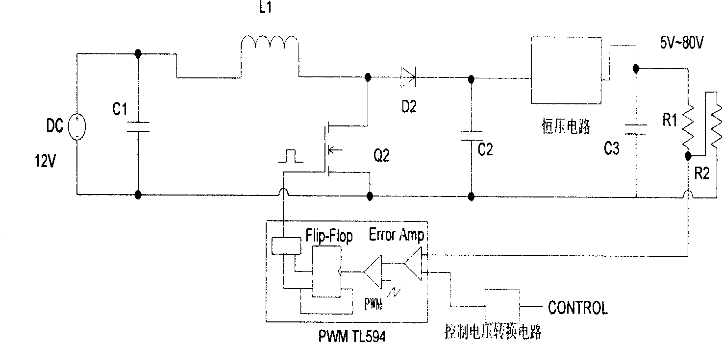
[0021] Below according to accompanying drawing and embodiment the present invention will be described in further detail:

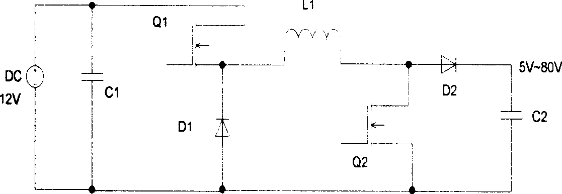
[0022] The voltage converter of the present invention is as figure 2 As shown, it is mainly composed of four parts of the circuit, namely the BOOST converter circuit (Boost Converter), the constant voltage circuit (Fixed Voltage Regulator Circuit), the control voltage conversion circuit (Voltage Shift Circuit) and the PWM controller (PWM Controller). The BOOST conversion circuit realizes the function of boosting the voltage. The constant voltage circuit is used to generate a fixed voltage difference to compensate the inherent deviation between the lowest output voltage and the input voltage of the BOOST circuit. The control voltage conversion circuit ensures that the control voltage and the output voltage are in a linear relationship. PWM controllers are used to implement feedback and control functions. The basic idea of ​​the present invention is that u...


PUM


Abstract

The invention discloses an inverter with continuous and adjustable output, comprising a BOOST converting circuit and a PWM controller. The first input end of the PWM controller is connected to the sampling end of the output voltage sampling circuit of the inverter, and the second input end of the PWM controller is a control end; the output signal of the PWM controller is used to control the switching tube in the BOOST converting circuit to make or break; a constant-voltage circuit is arranged at the output end of the BOOST converting circuit by serial connection, and the output of the constant-voltage circuit is taken as the output voltage of the convertor; the constant-voltage circuit is used to produce voltage difference; under a proper input voltage condition, the BOOST converter achieves the functions of a BUCK-BOOST circuit by constant-voltage circuit compensation. The invention has the advantages of a simple and reliable circuit, low electromagnetic interference and low cost; inaddition, linear-relation variation is achieved between the output voltage and the control voltage.

Description

technical field [0001] The invention relates to the improvement of a voltage converter circuit, in particular to a converter circuit with a wide range (linear) continuously adjustable output voltage. Background technique [0002] In many modern equipment application scenarios, under certain input voltage conditions, the output voltage is required to be continuously adjustable in a wide range, especially in medical equipment ultrasound systems that require multiple transmission pulses, and the transmission pulses are controlled by the output voltage through the FPGA. MOSFET The switch obtains that the output voltage is controlled by the control voltage and is continuously adjustable within a large range, and within its adjustment range, the output voltage may be higher or lower than the input voltage. [0003] At present, the implementation scheme of wide output voltage mainly adopts BUCK-BOOST converter, which can realize both boost function and step-down function. figure 1...

Claims


Application Information

Patent Timeline
Patent Type & Authority Patents(China)
IPC IPC(8): H02M3/155H02M3/156G05F1/56
Inventor 张皖李伟王安山
Owner SHENZHEN MINDRAY BIO MEDICAL ELECTRONICS CO LTD
Why Eureka
Try Eureka