
Exothermic weld mold clamp

A technology of exothermic welding and fastening clips, which can be used in welding equipment, auxiliary welding equipment, welding/cutting auxiliary equipment, etc., and can solve problems such as time-consuming

Inactive Publication Date: 2008-04-16
FRAMATOME CONNECTORS INT SA
View PDF1 Cites 4 Cited by
  • Summary
  • Abstract
  • Description
  • Claims
  • Application Information

AI Technical Summary

Problems solved by technology

The process of screwing thumbscrews into molded parts is a time consuming process

Method used


Image

  • Exothermic weld mold clamp
  • Exothermic weld mold clamp
  • Exothermic weld mold clamp

Examples


Embodiment Construction

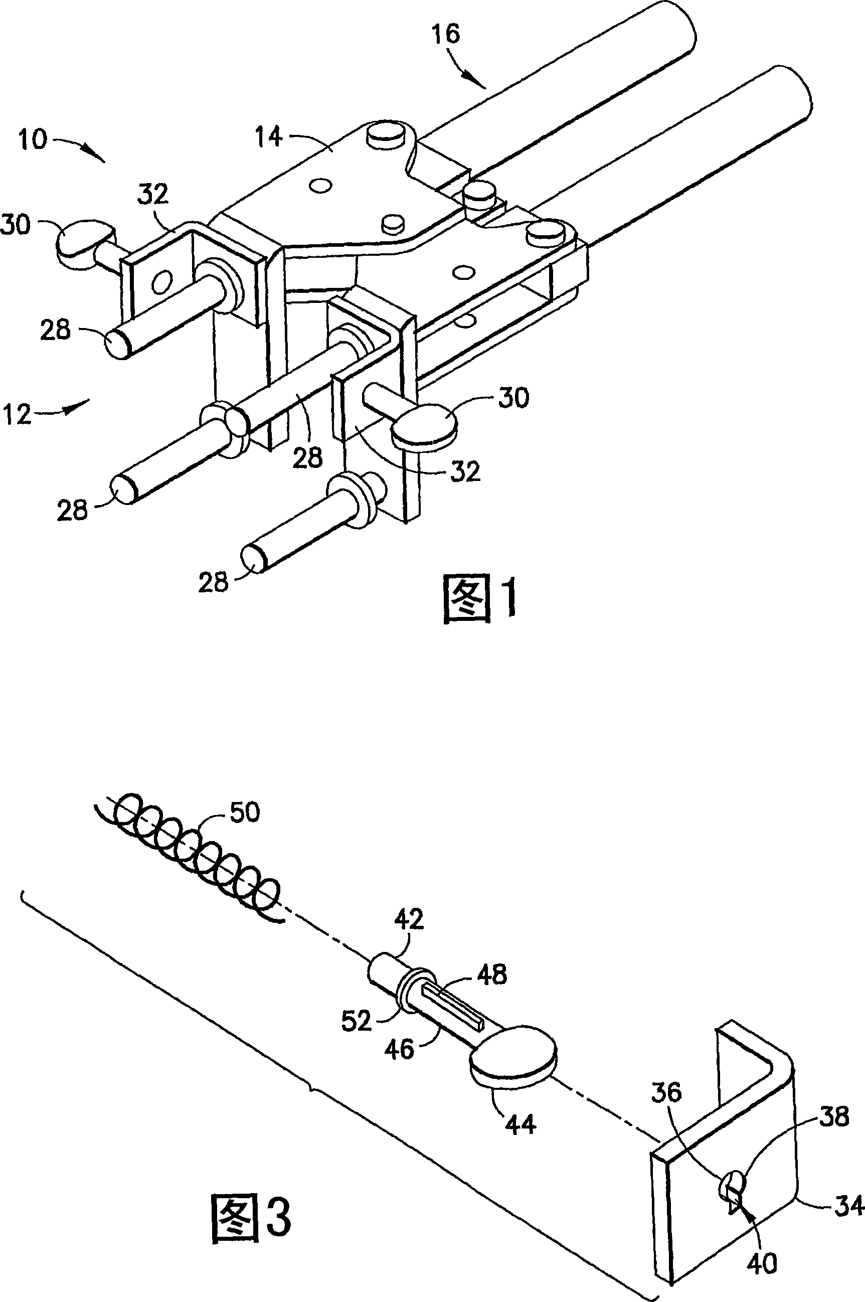
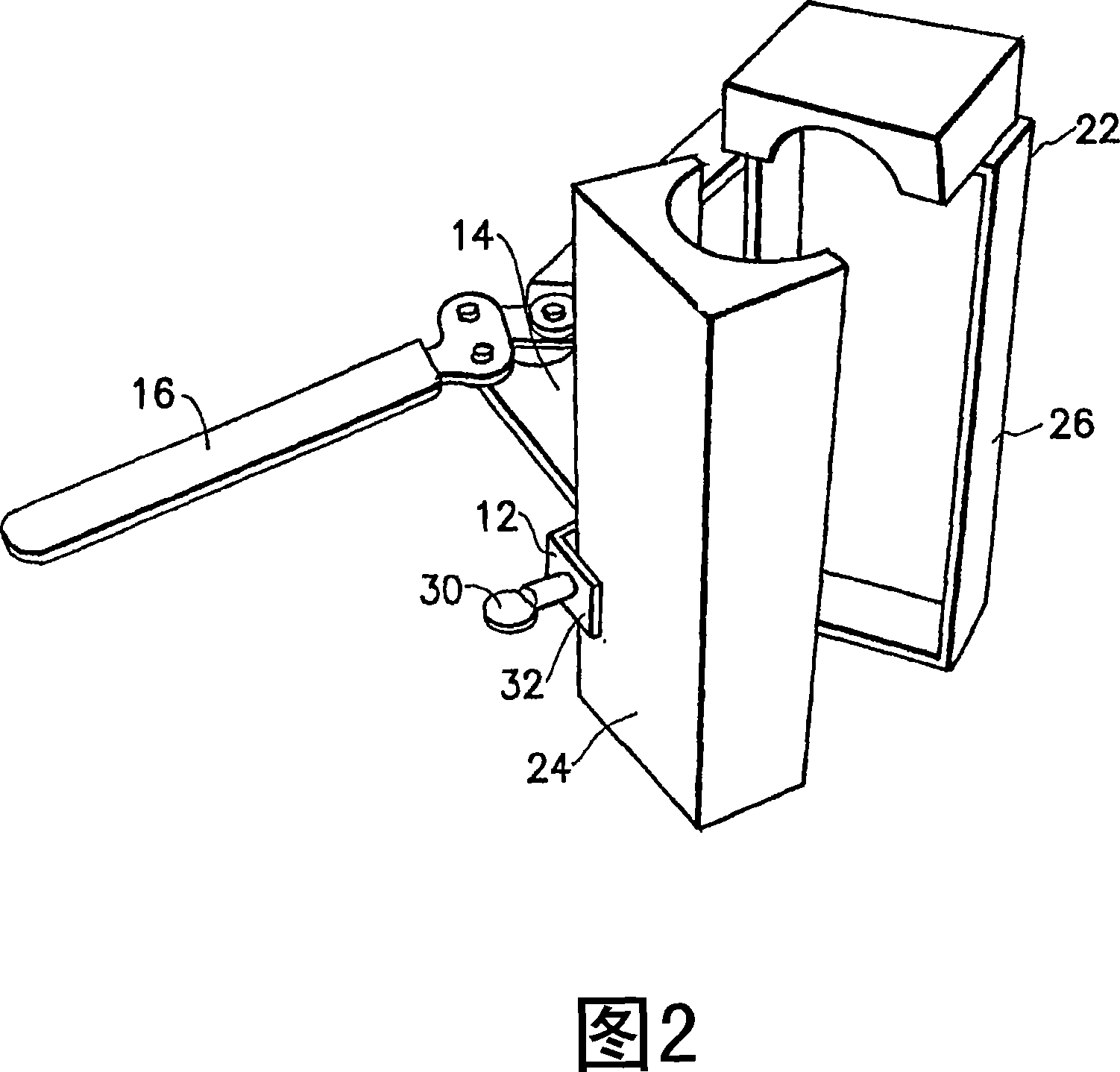
[0017] Referring to FIG. 1, a perspective view of a conventional exothermic welded die fastening clip 10 is shown. The fastening clip 10 includes an exothermic mold mounting portion 12 , a moving portion 14 , and a rear gripping portion 16 . The mold mounting part 12 includes a left part 18 and a right part 20 . Each section 18, 20 is adapted to individually mount a mold piece of an exothermic mold thereon. Referring also to FIG. 2 , the fastener 10 is shown coupled to the exothermic die 22 . The moving part 14 is adapted to move said left part 18 and right part 20 relative to each other to move the mold parts 24, 26 between an open position shown in Fig. 2 and a closed position relative to each other. Other types of fastening clips exist in the prior art. The present invention has been described with reference to the fastening clip shown in Figures 1 and 2 for illustrative purposes only and should not be construed as limiting the invention.

[0018] Typically, each side 1...


PUM


Abstract

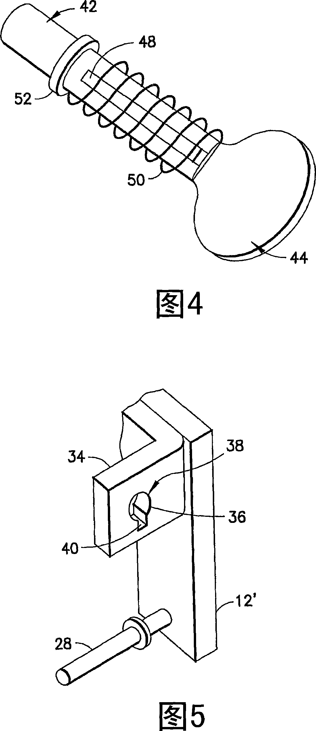
An exothermic weld mold clamp including a mold locating system adapted to locate pieces of an exothermic mold relative to each other; and a mold locking system. The mold locking system includes at least one mold locking pin movably mounted on the mold locating system and a spring biasing the locking pin towards a locking position with at least one of the exothermic mold pieces.

Description

technical field [0001] The present invention relates to exothermic welded mold fastening clips, and more particularly, the present invention relates to a mold locking system. Background technique [0002] US Patent Application No. 6382496B1 discloses an exothermic welding handle type fastening clip. Currently, die clamps are used to hold the sheets together in a multi-piece exothermic welding die so that they can be held together during the exothermic welding process. Conventional mold clamps or handle clamps employ threaded thumbscrews and are manually tightened or screwed into the mold part to clamp the mold part to the mold clamp. The process of screwing thumbscrews into molded parts is a time consuming process. This step is the single most time-consuming step in the entire exothermic soldering process that involves tightening the thumbscrews in place and loosening the thumbscrews after soldering installation. [0003] Accordingly, there is a need for a more rapid meth...

Claims


Application Information

Patent Timeline
IPC IPC(8): B23K37/04B23K37/00
CPCB23K37/0435
Inventor R·鲁兰
Owner FRAMATOME CONNECTORS INT SA
Learn More