Fastener

A technology for fasteners and components, applied in the field of fasteners, can solve problems such as inability to pull out, complex manufacturing, etc., and achieve the effect of large tolerances

Active Publication Date: 2008-04-16
ITW AUTOMOTIVE PRODS
View PDF2 Cites 6 Cited by
  • Summary
  • Abstract
  • Description
  • Claims
  • Application Information

AI Technical Summary

Problems solved by technology

When the screw is screwed into the nut, the nut will continue to rise along the slope of the retainer, making it impossible to pull out from the retainer
As the screw is tightened further, the face at the top of the nut wing element will compress against the part it is in contact with, this connection requires complex fabrication and special holes

Method used


Image

  • Fastener
  • Fastener

Examples


Embodiment Construction

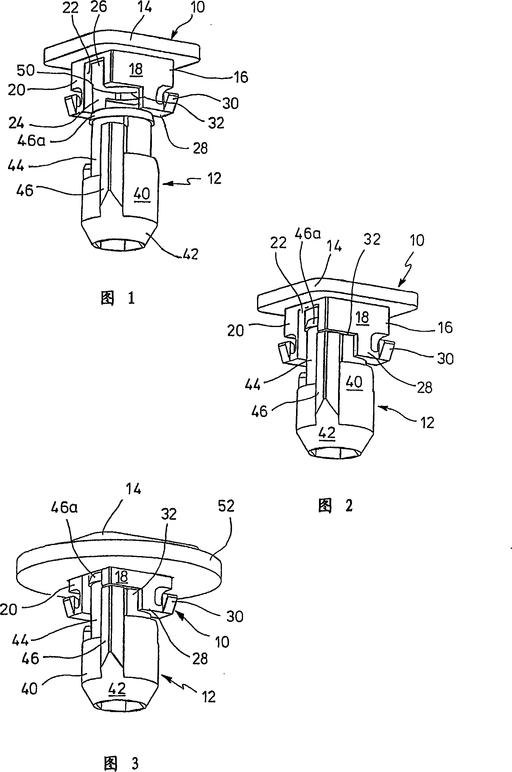
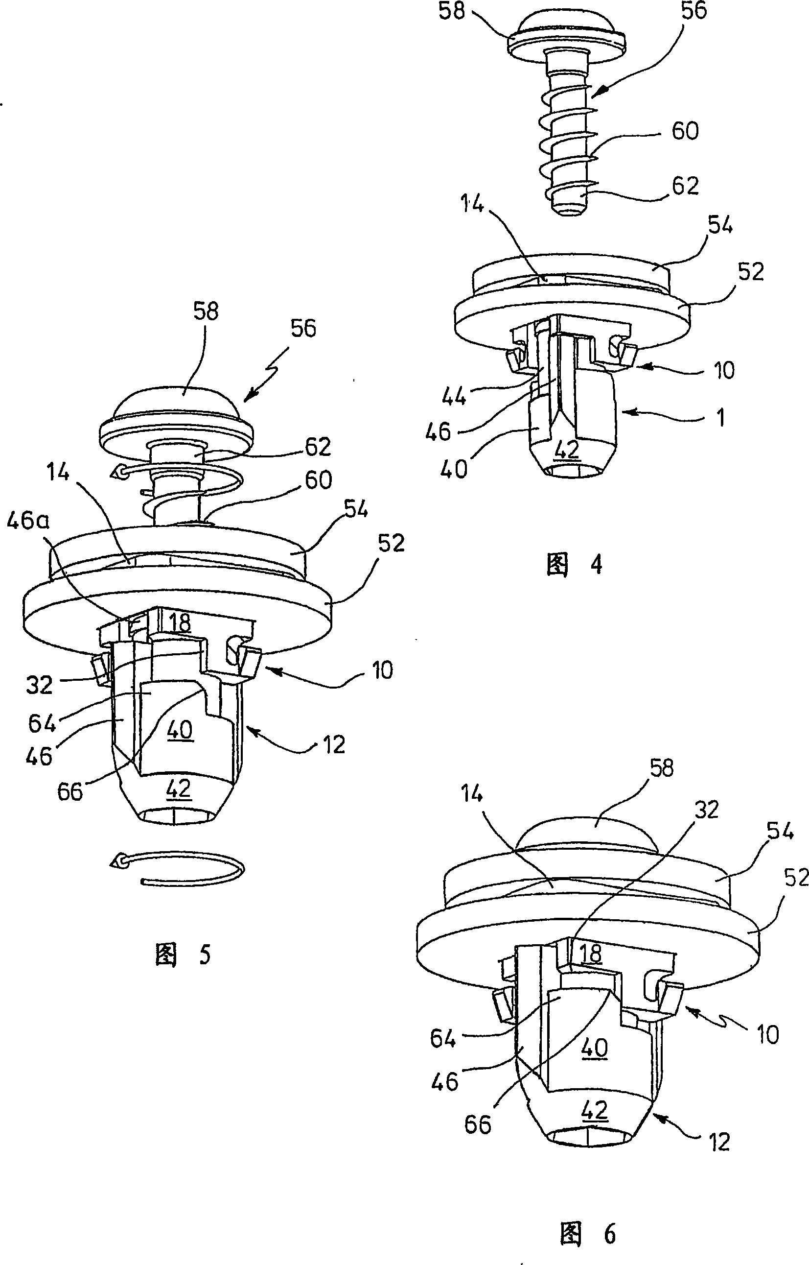
[0019] As shown in FIGS. 1 to 6 , the present invention includes a retainer 10 and a nut 12 . The holder 10 has a rectangular flange 14 and a shank 16 that is square in cross-section. The handle has two mutually opposite and continuous rectangular sides 18 and two other mutually opposite sides 20 separated by a gap 22, only one side 18 or 20 being shown in FIGS. 1 to 6 . It will be appreciated that certain opposing sides are the same.

[0020] In FIG. 1 , the shank 16 is substantially hollow and is defined by an inner cylindrical surface. The diameter of the first cylindrical surface 24 is slightly smaller than the diameter of the upwardly adjoining cylindrical surface 26 adjacent the flange 14 . As shown, cylindrical surfaces 24 are separated by gaps 26 .

[0021] At its end opposite the flange 14 , the handle 16 has a downwardly projecting projection 28 comprising a resilient hook 30 . The gap 32 is formed on the wall 18 in this way.

[0022] The nut 12 includes a lower...


PUM


Abstract

A fastener for connecting a first part (54) having a first hole to a second part (52) having a second hole, comprising a retainer (10) having at its end A radial flange (14) and a shank (16) of square or rectangular cross-section. This shank (16) can be inserted into a second hole of the second part to abut against a corresponding side of the second part. A nut (12) is at least partially received axially within the retainer and is rotatable from a first rotational position within the retainer to a second rotational position. The nut (12) has an axially drilled hole to accommodate a set screw (56) and includes on its outer side diametrically opposite wing elements (46) which, when the nut is rotated from a first rotational position to a second rotational position, the wing elements (46) ) will be pulled due to the set screw (56) resting against the outside of the second part, the head (58) of the set screw (56) pressing against the first part (54) and pressing the latter against the retainer flange.

Description

[0001] This application is based on and claims priority from German application No. 102005032699.4 filed on July 14, 2005, the content of which is hereby incorporated by reference. technical field [0002] The present invention relates to a fastener for connecting a first structural part, ie a rear first part, to a second structural part, ie a rear second part. Background technique [0003] European patent document EP0681110B1 describes a fastener of this type comprising two die-cast metal parts, one being a retainer and the other being a nut. The retainer has a radial flange which abuts against one side of the element when its shank passes through the hole of said element. The shank is rectangular in cross-section and tapers away from the flange. A nut containing threads and two wing elements can be inserted into a hollow retainer, in which the nut may be rotated 90 degrees about the axis, said wing elements are turned along a ramp until they fit into the retainer parallel...

Claims


Application Information

Patent Timeline
Patent Type & Authority Applications(China)
IPC IPC(8): F16B37/04
CPCF16B37/042F16B37/005F16B37/044F16B37/14F16B37/04F16B37/00
Inventor 艾伯特·斯邦克
Owner ITW AUTOMOTIVE PRODS
Why Eureka
Try Eureka