Microwave oven with a drain orifice

A technology for microwave ovens and discharge ports, which is applied in the field of microwave ovens to achieve good contact and prevent arc generation

Inactive Publication Date: 2008-04-16
PREMARK FEG L L C
View PDF1 Cites 0 Cited by
  • Summary
  • Abstract
  • Description
  • Claims
  • Application Information

AI Technical Summary

Problems solved by technology

However, doing so does not necessarily prevent bad contact

Method used


Image

  • Microwave oven with a drain orifice
  • Microwave oven with a drain orifice

Examples


Embodiment Construction

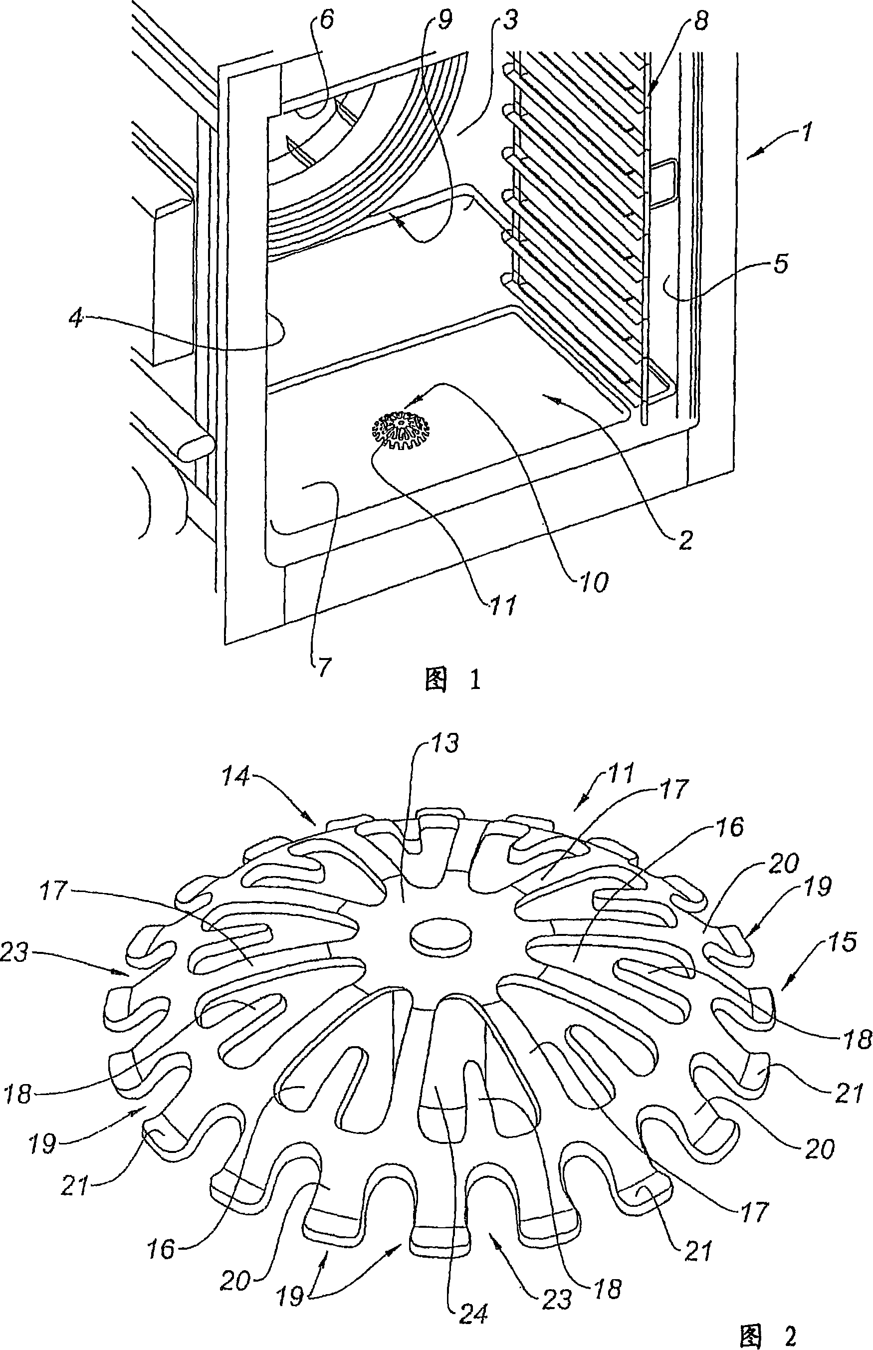
[0020] Referring to Fig. 1, the microwave oven 1 described here is a large public catering oven. It comprises a cooking or heating chamber 2 for food, this chamber 2 being formed by a rear wall 3 and two side walls 4, 5 (in particular the left side wall 4 and the right side wall 5 seen from the front), and a top plate 6 And bottom plate 7, and open towards the front. A door (not shown) is used to close the cavity 2 at the front during operation of the microwave oven 1 . The cavity 2 described here constitutes a volume of at least 0.15m 3 . The furnace comprises plate supports mounted on the side walls 4, 5, of which the right support 8 is as shown in Fig. 1 . The plate guides and supports, by means of these supports in the cavity 2, the food placed therein to be cooked, in a known manner.

[0021] The oven 1 described here is a combination oven, which in this case comprises steam heating means (not shown), convection heating means 9, and microwave generating means (not sho...


PUM


Abstract

The microwave oven of the invention comprises a food- cooking cavity, microwave-generating means, a floor with a discharge orifice to which is removably fixed a protective strainer (11) comprising a circumferential base (15) for contact with the floor, characterised in that the base (15) of the strainer (11) comprises a plurality of spring- forming feet (19) which form anti-electric arc means (19). Thus, the spring- forming feet (19) form ant i- electric arc means (19), since their elasticity produces a spring effect which makes it possible to compensate for the irregularities of the contact surface on the floor, and to ensure good contact, hence preventing the formation of electric arcs.

Description

technical field [0001] The present invention relates to the field of microwave ovens, and in particular to so-called large catering ovens, i.e. large capacity ovens (typically over 0.15m 3 ). Background technique [0002] Large public catering stoves are used in restaurants, canteens, restaurants, etc. [0003] There are several types of large communal eating stoves. Convection ovens include a gas oven or one or more heating resistors and one or more convection fans within the oven chamber. For steam heated furnaces, steam is generated either indirectly outside the furnace chamber or directly by spraying water onto a fan associated with a heating resistor or gas furnace. Some furnaces are combination models with convection and steam heating to enhance the performance of the furnace. [0004] In addition to one or both of the above heating methods, recent developments in large catering stoves have incorporated microwave heating. [0005] Recent developments in large cate...

Claims


Application Information

Patent Timeline
Patent Type & Authority Applications(China)
IPC IPC(8): H05B6/80
CPCH05B6/6402
Inventor 热拉尔·博斯米歇尔·乔治·福雷
Owner PREMARK FEG L L C
Why Eureka
Try Eureka