
Eureka
For R&D, Eureka makes reading and utilizing patents & technical documents easy.
Eureka AIR
Designed for self-driven R&D workflows. Generate viable solutions, solve complex R&D challenges, empower your innovation with AI.

Eureka Materials
Designed for material experts only. Revolutionize your material R&D, from search, analyze, to developing new materials.

TechResearch
Generate reliable direction feasibility study reports for your R&D in just a few steps.

TechSeek
Discover and master advanced knowledge NOW. Basics, ideas, possibilities, all at once.

TechMind
As an expert in R&D Theories, TechMind can generates customized viable solutions instantly.

TechRisk
Analyze your overall solution with one click, know your potential R&D risks in advance.

TechMonitor
Get weekly tech updates, stay abreast of the latest tech innovations and key insights.
Clutch controlling apparatus and clutch controlling method
A clutch control, clutch technology, applied in transmission control, components with teeth, belts/chains/gears, etc., can solve the problem of difficulty in verifying the reliability and stability of control actions, and achieve the effect of preventing speed change shocks
- Summary
- Abstract
- Description
- Claims
- Application Information
AI Technical Summary
Problems solved by technology
Method used
Image

Examples
no. 1 approach
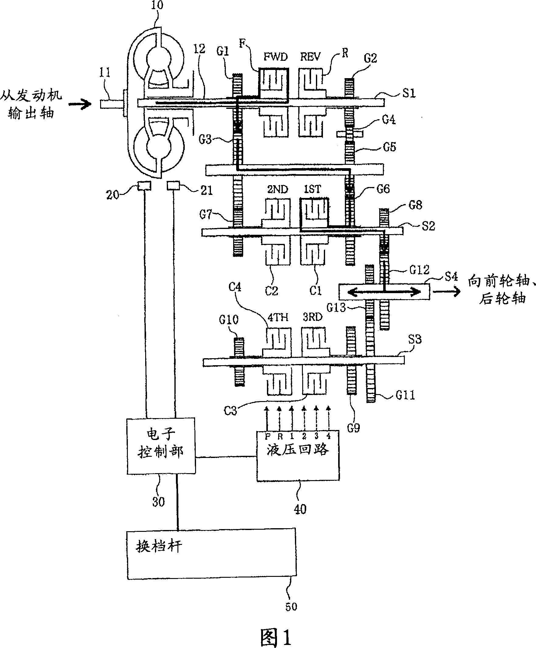
[0028] Hereinafter, preferred embodiments of the present invention will be specifically described with reference to the drawings. 1 to 5 show a first embodiment of the clutch control device of the present invention. As an example, as shown in FIG. 9 , the clutch control device 100 of the first embodiment is mounted on a transmission 110 of a construction vehicle such as a wheel loader. The output of the engine E of the wheel loader is decelerated by the transmission 110 and then transmitted to the wheels 120 .
[0029] A clutch control device 100 shown in FIG. 1 is a device that hydraulically controls hydraulic clutches C1 to C4 incorporated in a transmission 110 . The transmission 110 has, as its basic components, a torque converter 10, clutch shafts S1 to S3, an output shaft S4, a plurality of gears G1 to G13, a forward hydraulic clutch F, a reverse hydraulic clutch R, and 1st to 4th gears. Used hydraulic clutches C1~C4.
[0030] The clutch control device 100 includes an ...
no. 2 approach
[0057] Hereinafter, a clutch control device 100 according to a second embodiment of the present invention will be described with reference to FIGS. 6 and 7 .
[0058] In the clutch control device 100 of the second embodiment, as the engine speed for determining the above-mentioned combination control information S, instead of using the shift start time, a predicted speed a little time after the shift start time is used. Other configurations are the same as those of the above-mentioned first embodiment. The differences from the first embodiment will be mainly described below.
[0059] FIG. 6 is a graph showing changes in the engine speed with time before and after the start of shifting, with the vertical axis representing the rotational speed and the horizontal axis representing the time axis. In addition, FIG. 6 shows a case where the change in the engine rotational speed at the time of shifting is larger than the normal level. Such a large change in the engine rotational sp...
no. 3 approach
[0072] Next, a clutch control device according to a third embodiment of the present invention will be described.
[0073] The clutch control device according to the third embodiment is installed in a construction vehicle (for example, a wheel loader) capable of automatic mode setting for automatically selecting a speed level according to conditions such as vehicle speed and engine speed.
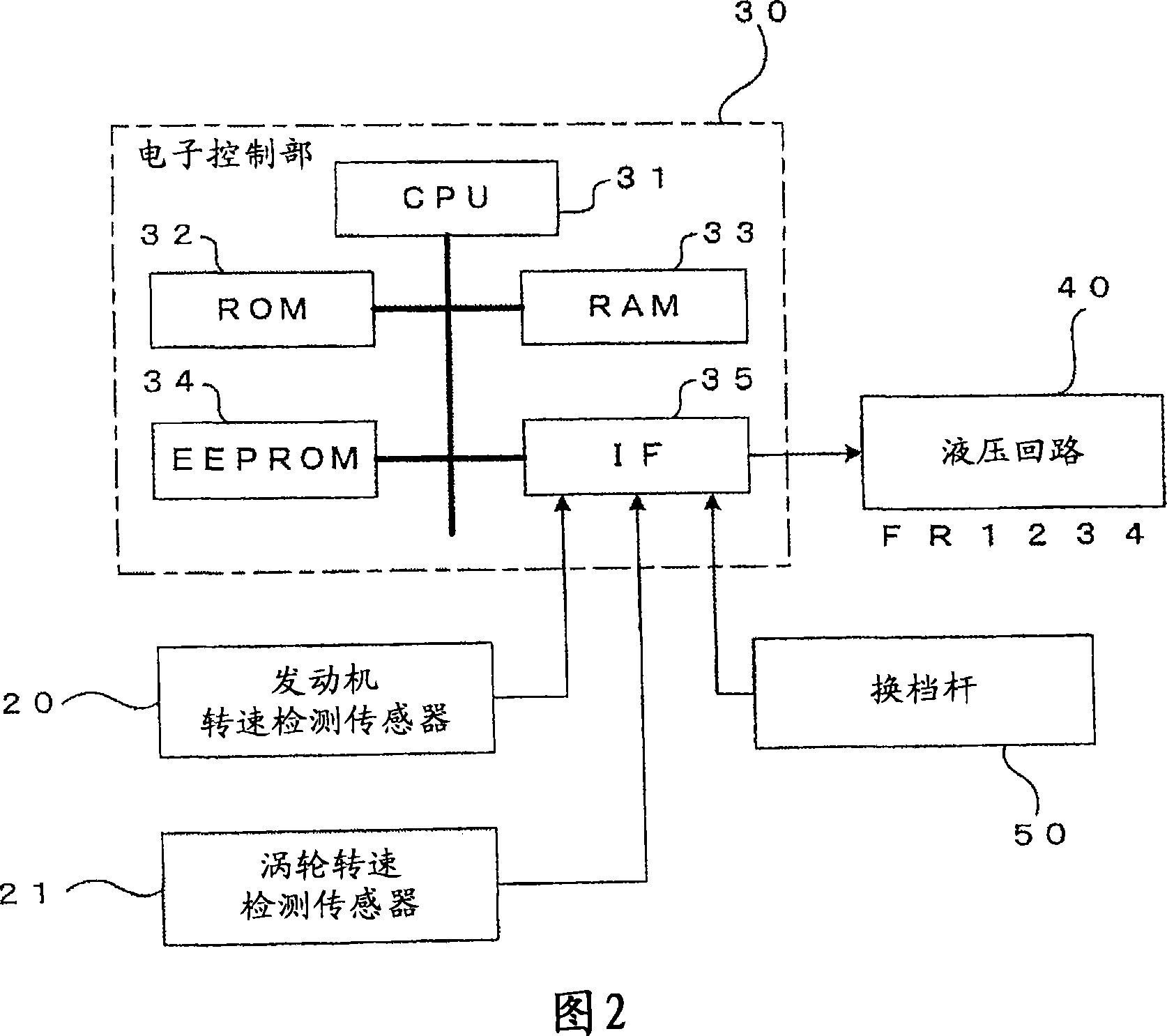
[0074] FIG. 8 is a block diagram showing an electrical configuration of a clutch control device according to a third embodiment. The automatic mode includes a driving mode suitable for construction vehicles and a working mode suitable for bucket operations, etc., and can be switched and selected by operating the mode switching switch 60 . An operation signal from the mode selector switch 60 operated by the operator is input to the electronic control unit 30 a of the clutch control device through the interface 35 .
[0075] In the RRPROM 34a of the electronic control unit 30, combination con...
PUM
 Abstract
Description
Claims
Application Information
 - R&D Engineer
- R&D Manager
- IP Professional
- Industry Leading Data Capabilities
- Powerful AI technology
- Patent DNA Extraction
Browse by: Latest US Patents, China's latest patents, Technical Efficacy Thesaurus, Application Domain, Technology Topic, Popular Technical Reports.
© 2024 PatSnap. All rights reserved.Legal|Privacy policy|Modern Slavery Act Transparency Statement|Sitemap|About US| Contact US: help@patsnap.com