
Automatic forming method for parallel U-shape lamp tube unit in energy-saving fluorescent lamp tube

A technology of energy-saving fluorescent lamps and molding methods, which can be used in glass molding, glass reshaping, manufacturing of ships or leading wires, etc. It can solve the problems of waste of materials, processing costs, and difficult control and improvement of heating and melting processes.

Inactive Publication Date: 2008-04-30
XIAMEN DONGLIN ELECTRONICS
View PDF0 Cites 6 Cited by
  • Summary
  • Abstract
  • Description
  • Claims
  • Application Information

AI Technical Summary

Problems solved by technology

[0003] In the above method, it is necessary to apply different heating temperatures according to the different bending degrees of different sections of the glass tube 103, that is, different sections are heated with flames of different temperatures, or different sections are heated with flames of the same temperature and the heating time is different. , or different sections are heated with flames of different temperatures and the heating time is also different. In this way, not only the process of heating and softening is not easy to control, but also, during the heating process of such a long glass tube 103, the molten glass The tube 103 will sag and deform under the action of gravity. In order to firmly support the glass tube 103 during heating, the length of both ends of the glass tube 103 must be lengthened so that the manipulator can firmly fix the glass tube 103 during the entire heating process. After being formed into a U-shaped tube, the excess glass tube is cut off, resulting in waste of material and increase in processing costs

Method used


Image

  • Automatic forming method for parallel U-shape lamp tube unit in energy-saving fluorescent lamp tube
  • Automatic forming method for parallel U-shape lamp tube unit in energy-saving fluorescent lamp tube
  • Automatic forming method for parallel U-shape lamp tube unit in energy-saving fluorescent lamp tube

Examples


Embodiment Construction

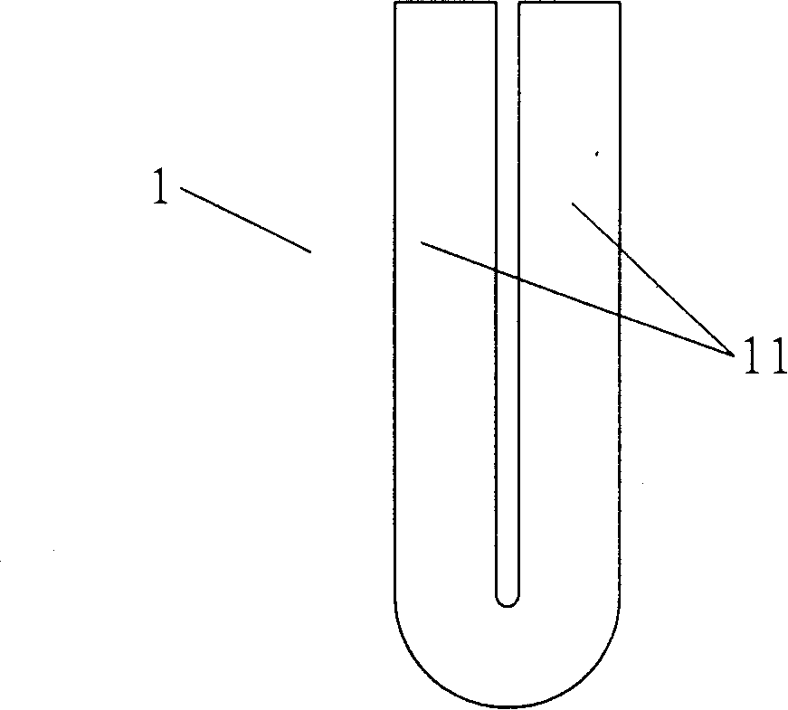
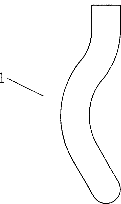
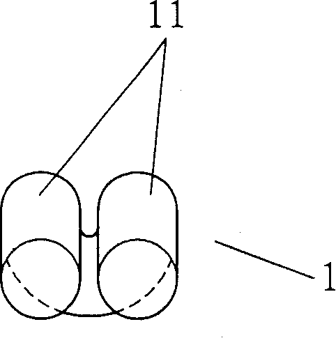
[0021] See Figure 1-3 As shown, it is a preferred embodiment of a single lamp tube unit to be processed and formed in the present invention. As for the lamp tube, it can be combined by four such lamp tube units 1 through bridges. The number of lamp tube units 1 is based on the design of the lamp tube As shown in FIG. 6 , each lamp unit 1 of the present invention is also formed by bending a single U-shaped tube with the help of molds 101 and 102 according to the same arc, so that the side tubes 11 of the same lamp unit 1 between parallel and compact (see figure 1 , 3 ), this paper shows that the arc of the lamp unit 1 is a circular arc (see figure 2 ), can also be quasi-elliptical arc, S-arc and broken line type, etc. (not shown in this article). The tube diameter of the side tube 11 of each lamp tube unit 1 is 6-12 mm. As described in PCT / CN2004 / 000696, each lamp unit 1 is connected by a bridge, and the side tubes 11 of the two lamp units 1 at the head and tail are equip...


PUM


Abstract

The invention discloses an automatic shaping method of parallel U-shaped tube unit of energy-saving fluorescent tube, which comprises that first a glass tube via a transmitter is fed into a heater, the bottom of parallel U-shaped tube is heated and softened, then the softened glass tube is bent into U-shape, to be fed into the heater, the side tube of the parallel U-shape tube is heated, and the softened U-shaped glass tube is straightly inserted between cavity die and terrace die of a shaping die, the cavity die and terrace die via a match / release mechanical arm clamps the bent glass tube in a U-shaped slot which two sides are bent at same curvature, a blow tube blows air into the glass tube to stuff and shape the bent portion of the glass tube according to the U-shaped slot, the cavity die and terrace die are separated by the match / release mechanical arm, and the glass tube released from die is a tube unit. The invention can reduce process cost, improve efficiency, and improve material utilization of energy-saving fluorescent tube.

Description

technical field [0001] The invention relates to the technical field of lighting lamps, in particular to an automatic molding method for parallel U-shaped lamp tube units in energy-saving fluorescent lamp tubes. Background technique [0002] Parallel U-shaped light tube units in existing fluorescent tubes such as Figure 1-3 As shown, it is mainly made by the method of automatic one-time molding, such as the international application number PCT / CN2004 / 000696, the name is "automatic one-time molding of energy-saving fluorescent lamp and U-shaped lamp unit molding method and mold". As shown in Figure 4, the process flow is as follows: the first step, the glass tube 103 is sent to the heater 105 by the conveying mechanism 104, and is heated and melted in sections according to the degree of bending of the glass tube 103. Larger parts are melted softer, such as: the bottom position of glass tube 103 corresponding to the U-shaped tube is melted the softest, and the position of glas...

Claims


Application Information

Patent Timeline
Patent Type & Authority Applications(China)
IPC IPC(8): C03B23/04C03B23/06H01J9/24
CPCC03B23/06
Inventor 何润林
Owner XIAMEN DONGLIN ELECTRONICS
Learn More