Feeding mechanism for sewing machine

A feeding mechanism and sewing machine technology, applied to sewing machine components, sewing machine housings, sewing machine control devices, etc., can solve problems such as low operating efficiency and troublesome cam replacement operations, and achieve operability

Inactive Publication Date: 2008-04-30
JUKI CORP
View PDF1 Cites 17 Cited by
  • Summary
  • Abstract
  • Description
  • Claims
  • Application Information

AI Technical Summary

Problems solved by technology

Therefore, the above-mentioned cam replacement work becomes troublesome, and the problem of low work efficiency occurs.

Method used


Image

  • Feeding mechanism for sewing machine
  • Feeding mechanism for sewing machine
  • Feeding mechanism for sewing machine

Examples


Embodiment approach 1

[0074] (Implementation 1: Effect)

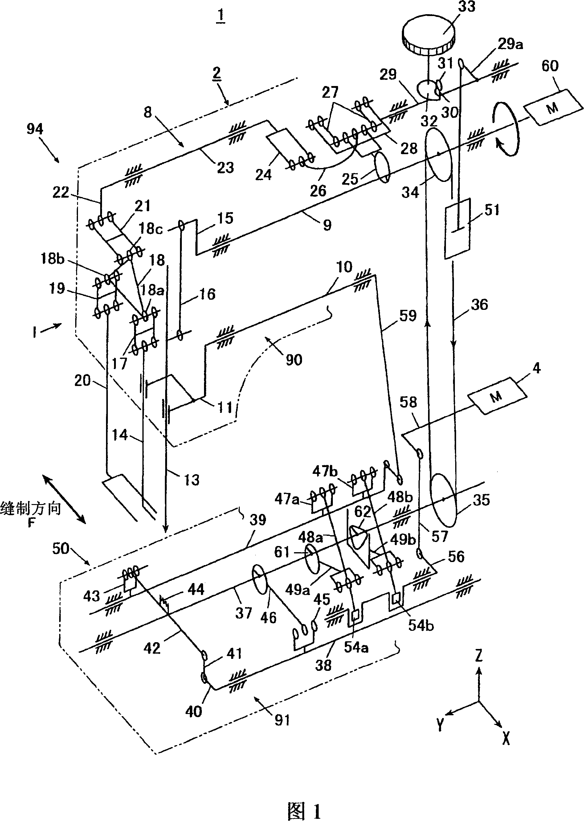
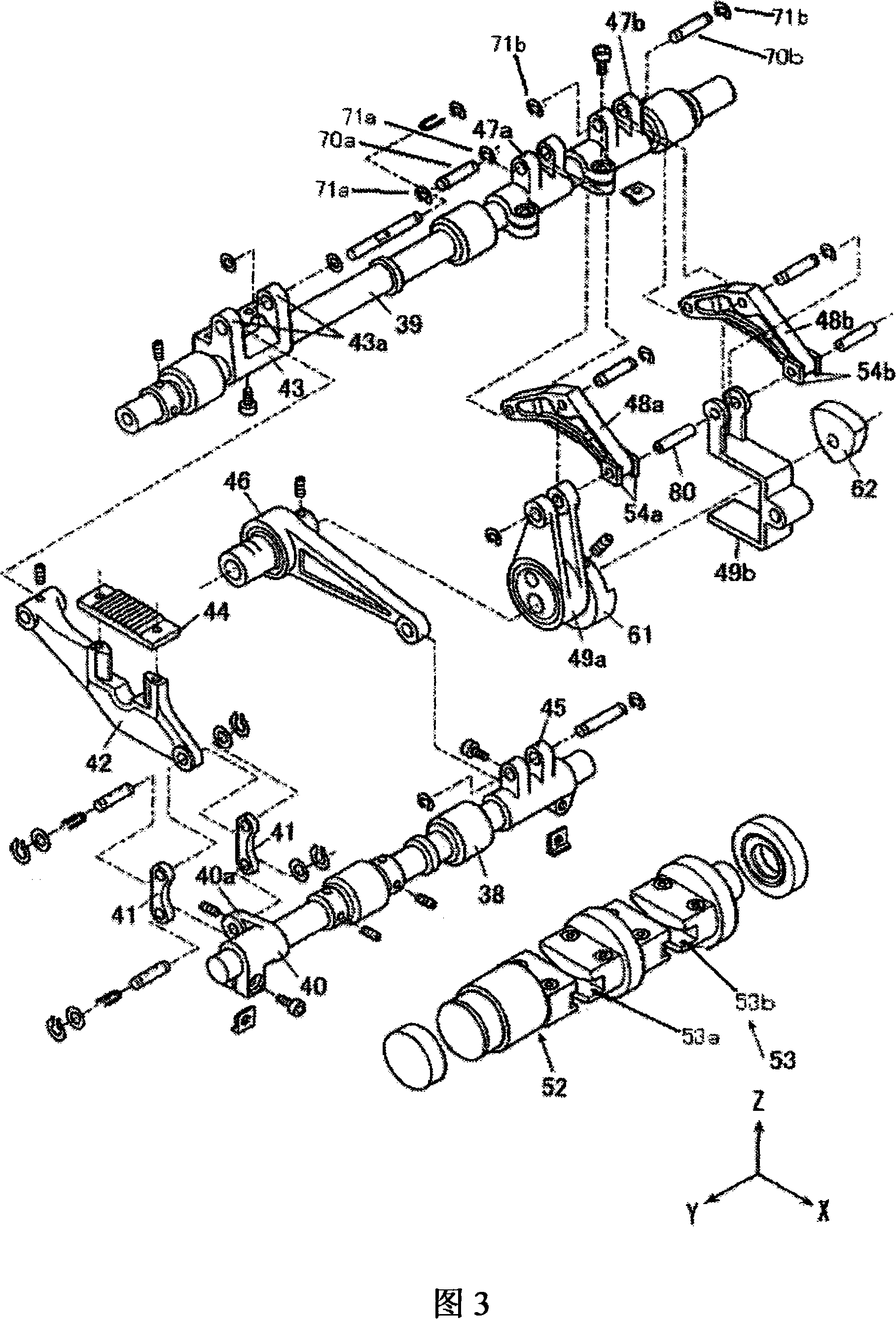
[0075] As described above, according to the combined feed sewing machine 1 according to Embodiment 1, by making the feeding operation of the upper feed leg 14 from the first horizontal feed link 48a into a connected state, the upper feed leg 14 can be moved by eccentricity. The feed action of the ellipse feed obtained by the cam 61, in addition, by making the feed action of the upper feed leg 14 from the second horizontal feed link 48b into a connected state, the upper feed leg 14 can be obtained by the triangular cam 62. The feed action of the rectangular feed. That is, since the eccentric cam 61 and the triangular cam 62 fixed coaxially are selectively used, the elliptical feed and the rectangular feed can be easily switched in one sewing machine, so the improvement of operability and the improvement of productivity can be realized. improve.

Embodiment approach 2

[0077] Next, Embodiment 2 using the present invention will be described based on FIGS. 8 and 9 .

[0078]A sewing machine 101 according to Embodiment 2, as shown in FIG. 8 , is different from Embodiment 1 in that the eccentric cam 161 and the triangular cam 162 are disposed adjacent to each other in the axial direction and can be axially relative to the lower cam. The shaft 37 is moved and positioned, and the switching unit changes its axial position by sliding the eccentric cam 161 and the triangular cam 162 relative to the lower shaft 37 along the axial direction, and the cams engaged with the horizontal feed link 149 as a transmission part , switch to the eccentric cam 161 or the triangular cam 162, thereby switching the movement trajectory of the upper feed foot 14.

[0079] Specifically, as shown in FIG. 8 , a substantially circular eccentric cam 161 and a triangular cam 162 are arranged adjacent to each other in the axial direction, and an integrated cam portion 160 is p...

Embodiment approach 3

[0086] Next, Embodiment 3 using the present invention will be described based on FIGS. 10 and 11 .

[0087] In the sewing machine 201 according to Embodiment 3, the eccentric cam 261 and the triangular cam 262 are adjacent to each other in the axial direction, and the horizontal feed link 249 as a transmission member has a frame portion 255, and within the frame of the frame portion 255, there are: The engaging part 249a engages with the eccentric cam 261; the second engaging part 249b engages with the triangular cam 262; the first engaging escape part 249c engages with the second engaging part 249b on the triangular cam 262 When the eccentric cam 261 is engaged with the horizontal feed link 249; and the second engaging escape portion 249d, when the eccentric cam 261 is engaged with the first engaging portion 249a, it prevents the triangular cam 262 from engaging with the horizontal feed link 249. Engage the connecting rod 249 . The difference between this embodiment 3 and th...


PUM


Abstract

The movement track of a feed pin is switched easily from an eccentric type to a rectangular type. The sewing machine comprises: a feed pin, contacting against and feeding the article to be sewn from the top position; an up-down feed part, making the feed pin do a feed action in the up-down direction; a horizontal feed part with an eccentric cam and a triangular cam fixed coaxially with the eccentric cam, and the cams make the feed pin do a swing action in the horizontal direction; a first horizontal feed connecting rod and a second horizontal feed connecting rod, activating following the eccentric cam and the triangular cam which are driving parts, and make the horizontal feed part do a swing action; and a switching part, switching and using each cam selectively. Thereby, two feed movement tracks of an eccentric feed and a rectangular feed are switched selectively in a sewing machine by switching an eccentric cam making the movement track of the feed pin to be an eccentric type and a triangular cam making the movement track of the feed pin to be a rectangular type.

Description

technical field [0001] The invention relates to a feeding mechanism of a sewing machine which feeds a sewing object through the feeding action of an upper feeding foot. Background technique [0002] At present, for example, as shown in JP-A-4-164485, there is known a feeding mechanism of a sewing machine, which has a horizontal feeding mechanism that horizontally abuts the upper feeding foot of the object to be sewn (cloth) from above. The reciprocating motion in the direction; and the up and down feed mechanism, which makes the upper feed foot reciprocate in the up and down direction, and makes the upper feed foot perform the feed motion along the elliptical orbit by synthesizing the above-mentioned horizontal direction and the above-mentioned up-down direction movement. [0003] The feeding mechanism of the above-mentioned existing sewing machine, through the eccentric cam fixed on the lower shaft driven by the sewing machine motor, transmits the reciprocating motion in th...

Claims


Application Information

Patent Timeline
Patent Type & Authority Applications(China)
IPC IPC(8): D05B27/00D05B33/00D05B69/00
CPCD05B27/02D05B73/12
Inventor 新井富夫
Owner JUKI CORP
Why Eureka
Try Eureka