
Thin transformer and transformer component

一种变压器、薄形化的技术,应用在变压器领域,能够解决厚度难以再缩减等问题,达到增加弹性应用的空间的效果

Inactive Publication Date: 2008-04-30
ACBEL POLYTECH INC
View PDF0 Cites 4 Cited by
  • Summary
  • Abstract
  • Description
  • Claims
  • Application Information

AI Technical Summary

Problems solved by technology

Therefore, the thickness of electronic products using these two types of transformers will face the problem that it is difficult to reduce the thickness, which needs to be further solved

Method used


Image

  • Thin transformer and transformer component
  • Thin transformer and transformer component
  • Thin transformer and transformer component

Examples


Embodiment Construction

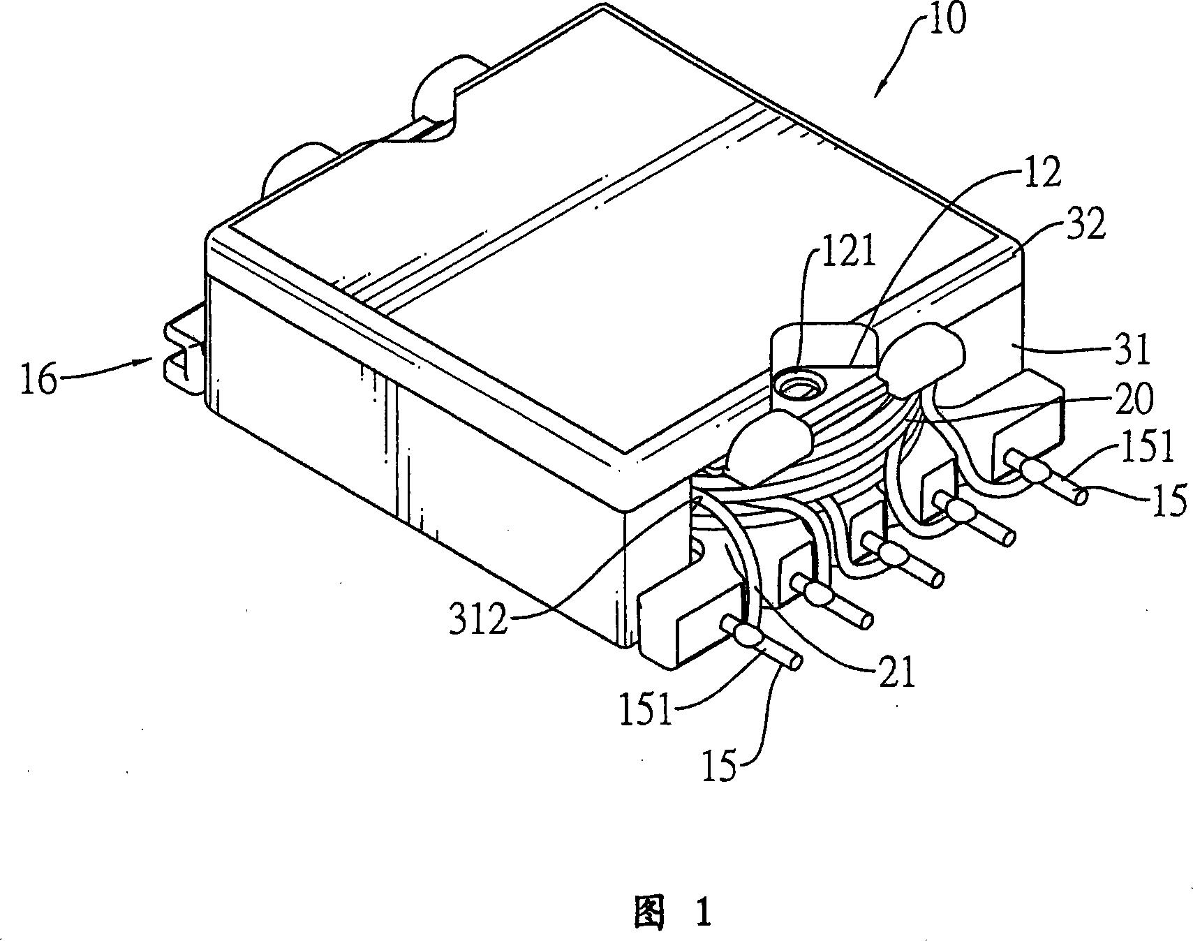
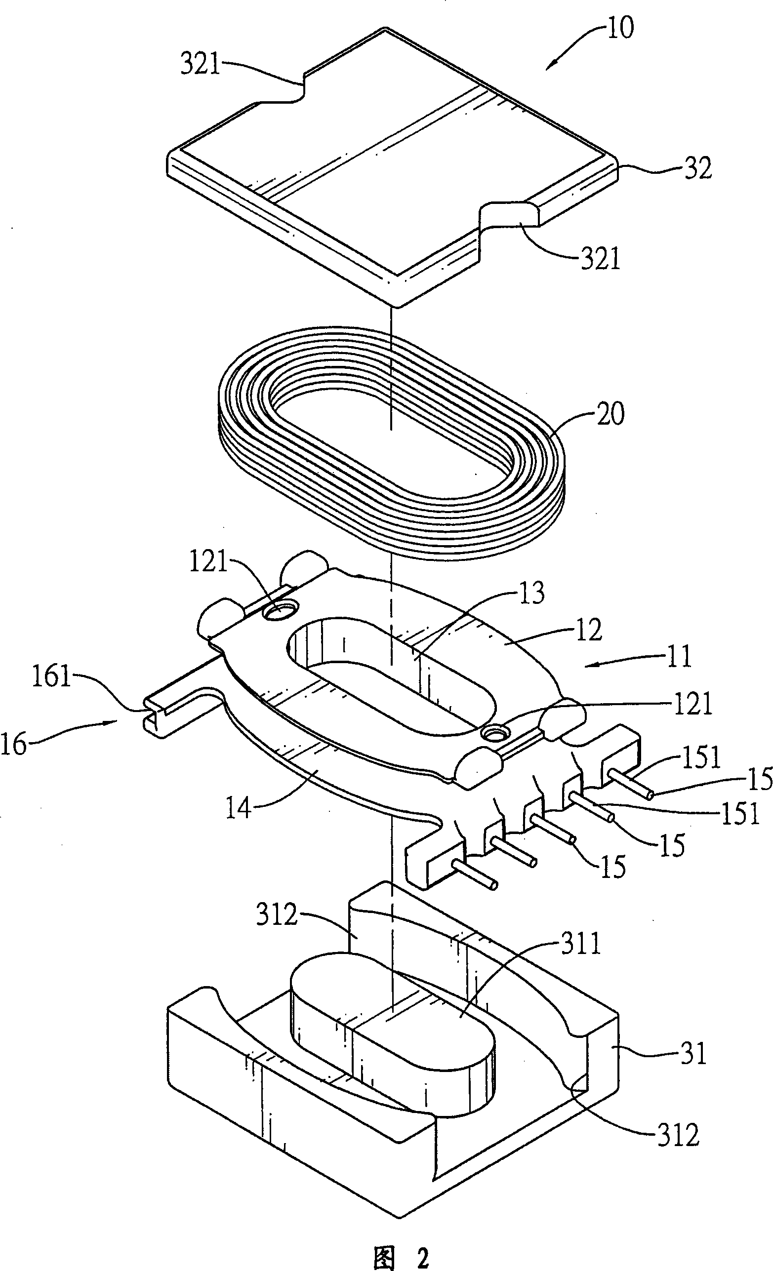
[0024] First please refer to Figures 1 and 2, which are the first preferred embodiment of the thin transformer 10 of the present invention, which includes:

[0025] The wire frame 11 has an I-shaped section and is composed of an upper ring 12, a hollow column 13 and a lower ring 14, wherein at least one side of the lower ring 14 is horizontally provided with a plurality of pins 15, and the upper end surface of each pin is a welding surface 151; and the two opposite sides of the upper ring 12 are respectively formed with wire holes 121; in this embodiment, one side of the lower ring 14 is provided with a plurality of pins 15, and the other opposite side is provided with a connecting piece 16, The coupling part 16 is a clamping part, and its outer surface forms an embedded groove 161 inwardly;

[0026] The coil 20 is wound on the outer wall of the hollow column 13 of the wire frame 11, and part of the coil end 21 is connected to the corresponding pin 15. As shown in FIG. The wi...


PUM


Abstract

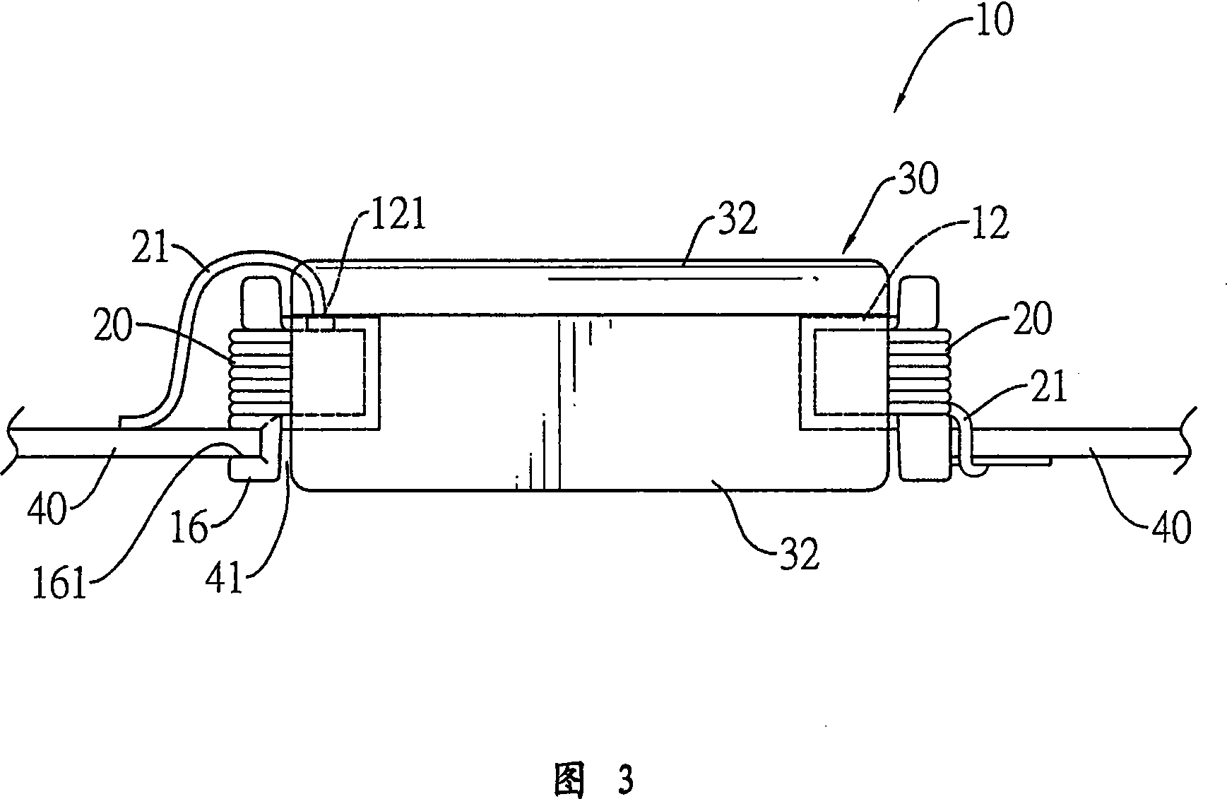
The transformer has a bobbin, a coil assembly and a magnetic core assembly. The bobbin is mounted in the magnetic core assembly and has multiple connecting pins being formed on at least one side of a bottom surface of the bobbin. Each connecting pin has a top surface as a soldering surface that corresponds to a solder pad on a back of a circuit board. At least one fastener is further formed on the bottom surface of the circuit board. Therefore, when the transformer is mounted through the circuit board, the connecting pins are soldered on the back of the circuit board to reduce the total thickness of the combination of the transformer and the circuit board.

Description

technical field [0001] The invention relates to a transformer, in particular to a thinned transformer and a transformer assembly capable of reducing welding to a circuit board and effectively reducing the overall thickness. Background technique [0002] As the current electronic products are becoming thinner and thinner, the requirements for the miniaturization of electronic parts are increasing. Since the general integrated circuit components can be miniaturized by the ever-changing semiconductor technology, and the passive components such as resistors and capacitors can be constructed by means of construction or other thin shapes However, there are still some components in the circuit that cannot achieve the goal of significantly reducing the size as expected. [0003] Taking a transformer as an example, in order for the transformer to reach its predetermined rated voltage and current value, the number of coil turns cannot be reduced, so the overall size can only be change...

Claims


Application Information

Patent Timeline
Patent Type & Authority Applications(China)
IPC IPC(8): H01F30/06H01F27/30H01F27/24
CPCH01F5/04H01F30/06H01F27/325H01F27/29H01F2005/043H01F2027/065H01F41/10
Inventor 杨朝元张顺德叶长青陈瑞家
Owner ACBEL POLYTECH INC
Learn More