
A method for realizing image layer overlapping

A technology of layer overlay and layer, which is applied in the direction of image communication, color TV parts, TV system parts, etc., can solve the problems of complex implementation and large amount of calculation, and achieve easy implementation, simple operation, and large amount of calculation Reduced effect

Inactive Publication Date: 2008-04-30
ZTE CORP
View PDF0 Cites 28 Cited by
  • Summary
  • Abstract
  • Description
  • Claims
  • Application Information

AI Technical Summary

Problems solved by technology

[0004] When using this method to superimpose layers, it is necessary to perform corresponding superposition processing pixel by pixel, which requires a large amount of calculation and complex implementation.

Method used


Image

  • A method for realizing image layer overlapping
  • A method for realizing image layer overlapping

Examples


Embodiment Construction
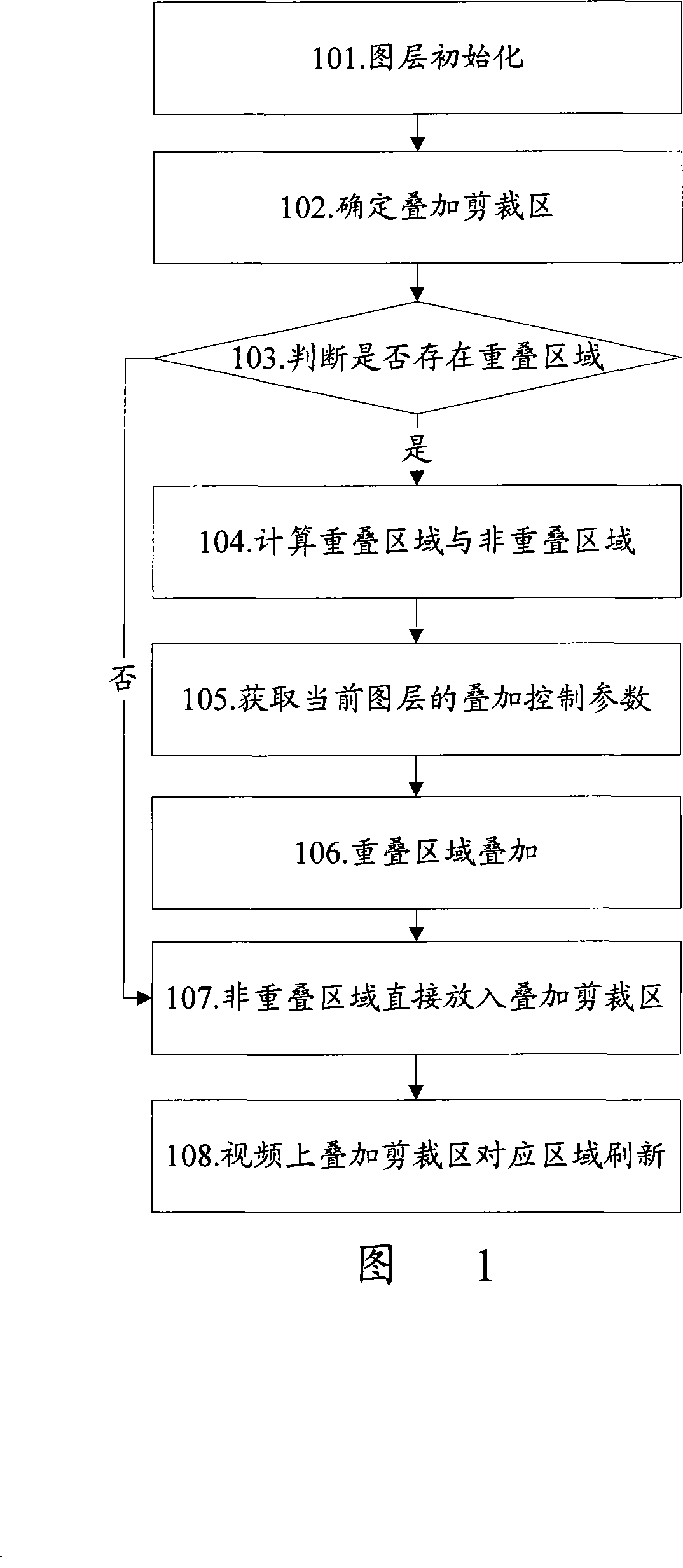
[0025] The basic idea of ​​the present invention is: determine the overlay clipping area, calculate the overlapping area and the non-overlapping area between the expected overlay area of ​​the current layer and the non-current layer; superimpose the corresponding overlapping area of ​​the current layer and the non-current layer Then put it into the corresponding position of the superimposed clipping area, and put the non-overlapping area of ​​the current layer directly into the corresponding position of the superimposed clipping area; after that, use the current superimposed clipping area to refresh the area corresponding to the superimposed clipping area on the video.

[0026] The implementation of the layer overlay method of the present invention will be described in detail below through specific embodiments and with reference to the accompanying drawings.

[0027] Fig. 1 is a schematic flow chart of the method for realizing layer overlay of the present invention, as shown in...


PUM


Abstract

The invention provides a method for overlaying image layers, which comprises: A, obtaining expected overlay areas of a current and a non-current on video and determining an overlay clipping area on video; B, calculating an overlay area and a non-overlay area between the expected overlay areas of the current layer and the incurrent layer; and C, overlaying the overlay area of the layers and placing in the relevant position in the overlay clipping region and directly placing the non-overlay area of the current layer in the relevant position in the overlay clipping region. The inventive method is easy to operate and realize.

Description

technical field [0001] The invention relates to layer overlay technology on video, in particular to a method for realizing layer overlay. Background technique [0002] Superimposition of layer signals on video signals is a problem often encountered in multimedia communications. However, how to reasonably and effectively realize the superimposition of layers on the video signal has been under discussion. [0003] At present, the technologies for superimposing video signals and graphic signals mainly include Alpha Blending (AlphaBlending) technology. The processing process of the Alpha mixing technology is: firstly, the RGB three color components of the source pixel and the target pixel are separated; after that, the three color components of the source pixel are respectively multiplied by the value of Alpha, and the three color components of the target pixel are The components are multiplied by the inverse value of Alpha; the calculation results obtained after the above mul...

Claims


Application Information

Patent Timeline
IPC IPC(8): H04N5/262G09G5/397
Inventor 董秀兰侯建文刘卫朱晓斌
Owner ZTE CORP
Features
  • Generate Ideas
  • Intellectual Property
  • Life Sciences
  • Materials
  • Tech Scout
  • Unparalleled Data Quality
  • Higher Quality Content
  • 60% Fewer Hallucinations
Learn More