Wiring box and method of mounting wiring box
An installation method and a wiring box technology are applied in the field of wiring boxes and can solve problems such as difficult installation
- Summary
- Abstract
- Description
- Claims
- Application Information
AI Technical Summary
Problems solved by technology
Method used
Image

Examples
no. 1 approach
[0075] The first embodiment described above has the following advantages.
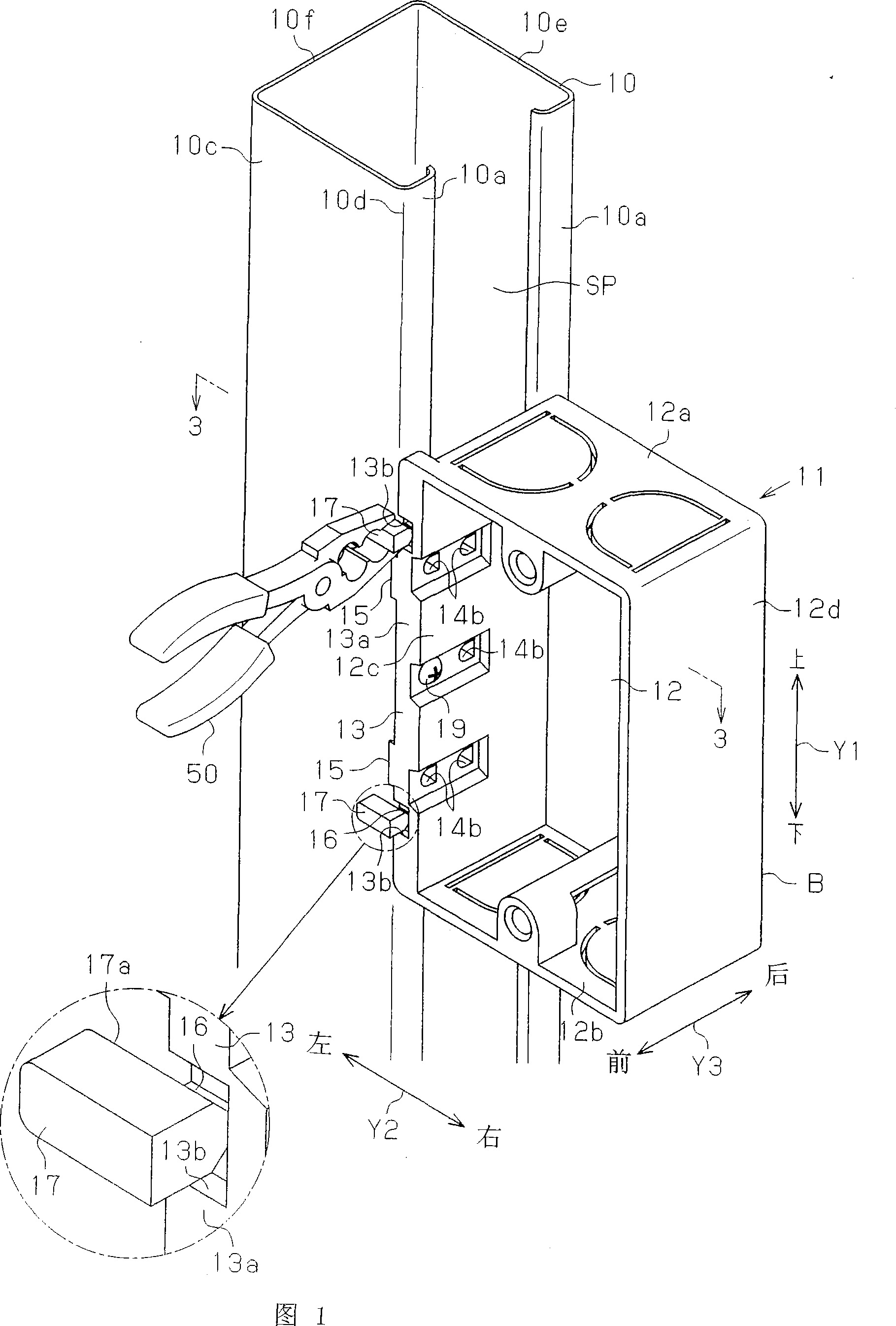
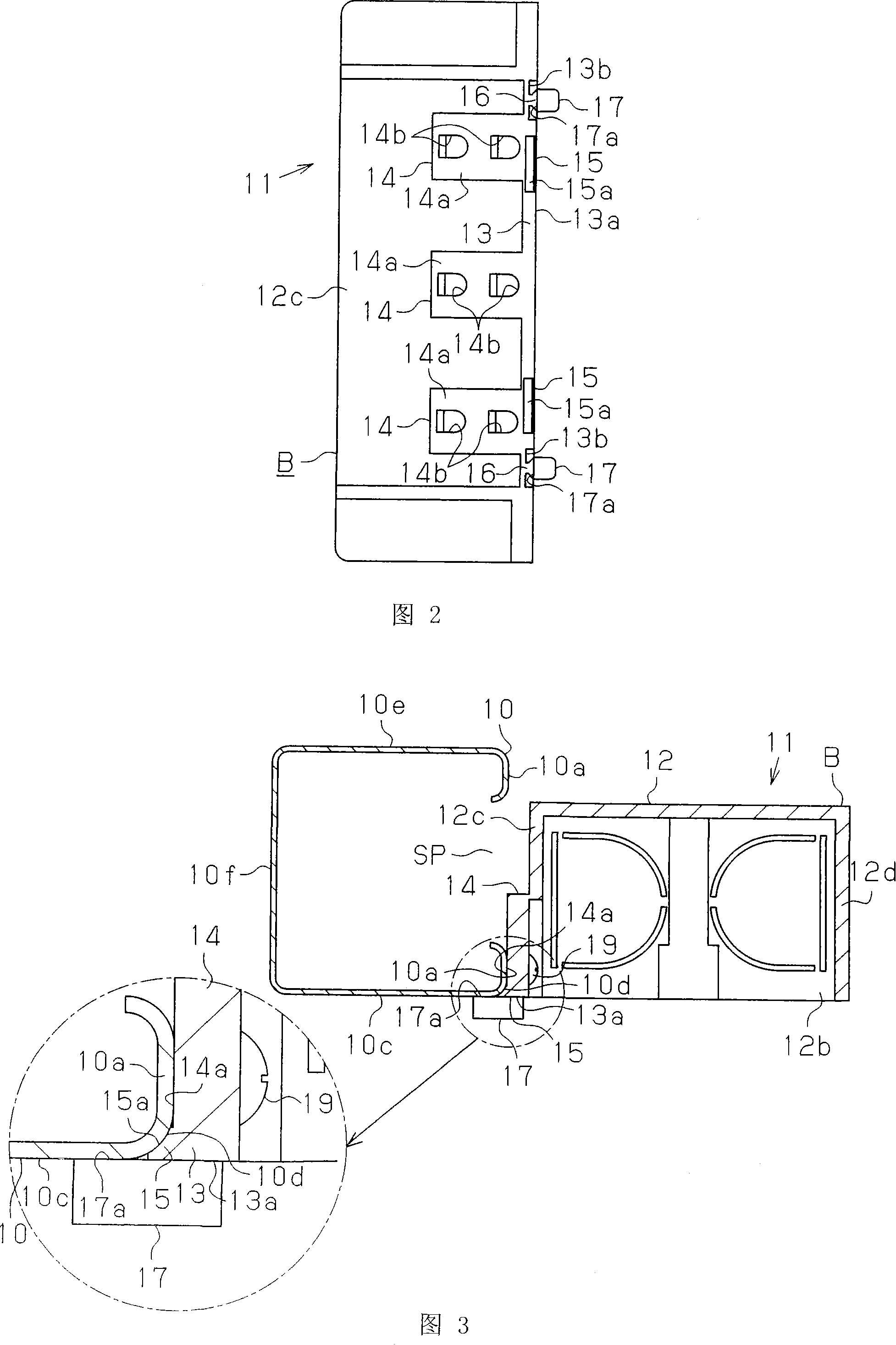
[0076] (1) The engaging portion 17 is provided on the front side of the case B. As shown in FIG. The back of the fastening part 17 (fastening surface 17a) is made so that it can be positioned on the same plane as the end surface on the front side of the box body B. As shown in FIG. If the abutting surface 14a of the distribution box 11 is abutted against the side (flange portion 10a) of the light steel profile 10, and the fastening surface 17a of the distribution box 11 is fastened to the front 10c of the light steel profile 10, the box The end face on the front side of the body B can be kept on the same plane as the front face 10c. That is to say, the operation of installing the wiring box 11 to the light steel profile 10 can be easily performed so that the end surface of the front side of the box body B and the front face 10c of the light steel profile 10 become a plane. In addition, the engaging p...
no. 2 approach
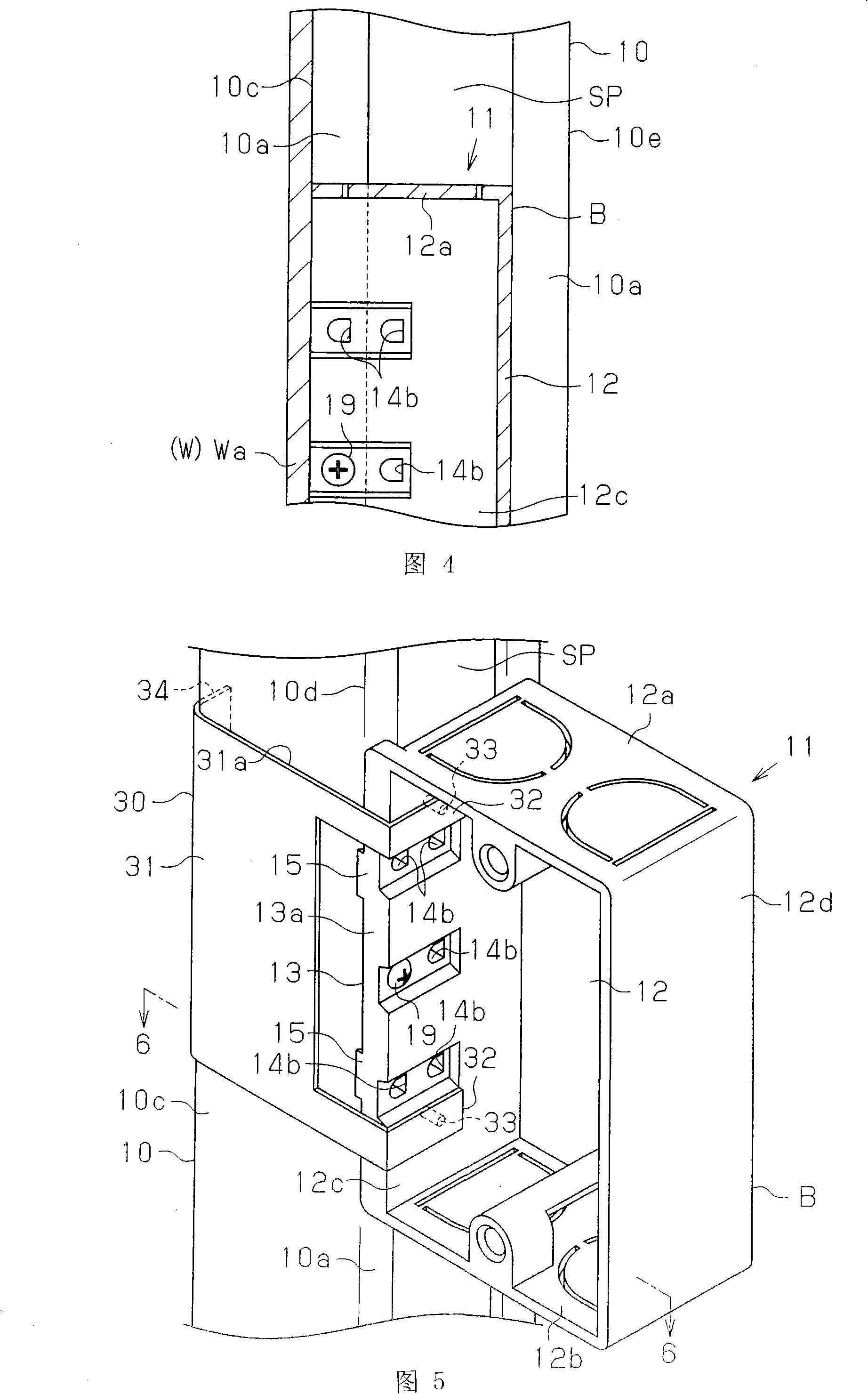
[0093] The second embodiment has the following advantages.
[0094] (10) The engaging member 30 is provided on the front side of the case B. As shown in FIG. The engaging surface 31a serving as the rear surface of the engaging member 30 is positioned on the same plane as the end surface on the front side of the case B. As shown in FIG. The abutting surface 14a of the wiring box 11 is abutted against the side (flange portion 10a) of the light steel section 10, and the fastening surface 31a of the fastening component 30 is fastened to the front 10c of the light steel section 10. Therefore, it is easy to make the end surface on the front side of the box B and the front surface 10c of the box B flush with each other. In addition, the engaging member 30 is coupled to the front side of the case B by a coupling structure formed by a concave-convex coupling relationship between the coupling protrusion 33 and the coupling hole 12f. By releasing the above-mentioned fastening relations...
no. 3 approach
[0101] The third embodiment has the following advantages.
[0102] (11) The holding piece 43 is formed on the engaging portion 40 . Therefore, the holding piece 43 can be easily held by the pliers 50 . That is, by holding the holding piece 43 with the pliers 50, the operation of cutting off the engaging portion 40 can be easily performed. As a result, the operation of removing the engaging portion 40 from the wiring box 11 is made easy.
[0103] Hereinafter, a fourth embodiment embodying the present invention will be described with reference to FIGS. 10 to 16 .
[0104] First, the lightweight partition wall W will be described. As shown in Figure 10, the lightweight partition wall W includes the following parts: a pair of slideways R fixed on the ceiling (not shown) and the floor (not shown); A plurality of light steel profiles 10; and a wall plate Wa erected by being fixed on the light steel profiles 10 and the above-mentioned slideway R. The above-mentioned wall panel W...
PUM
 Abstract
Description
Claims
Application Information
 - R&D
- Intellectual Property
- Life Sciences
- Materials
- Tech Scout
- Unparalleled Data Quality
- Higher Quality Content
- 60% Fewer Hallucinations
Browse by: Latest US Patents, China's latest patents, Technical Efficacy Thesaurus, Application Domain, Technology Topic, Popular Technical Reports.
© 2025 PatSnap. All rights reserved.Legal|Privacy policy|Modern Slavery Act Transparency Statement|Sitemap|About US| Contact US: help@patsnap.com