Method of printing decoration in mould

A printing method and in-mold decoration technology, applied in coating and other directions, can solve problems such as poor production efficiency

Inactive Publication Date: 2008-05-07
ASUSTEK COMPUTER INC
View PDF0 Cites 1 Cited by
  • Summary
  • Abstract
  • Description
  • Claims
  • Application Information

AI Technical Summary

Problems solved by technology

That is, the production efficiency of the product is not good

Method used


Image

  • Method of printing decoration in mould
  • Method of printing decoration in mould
  • Method of printing decoration in mould

Examples


Embodiment Construction

[0016] In order to make the above-mentioned purpose, features and advantages of the present invention more comprehensible, preferred embodiments will be described in detail below together with the accompanying drawings.

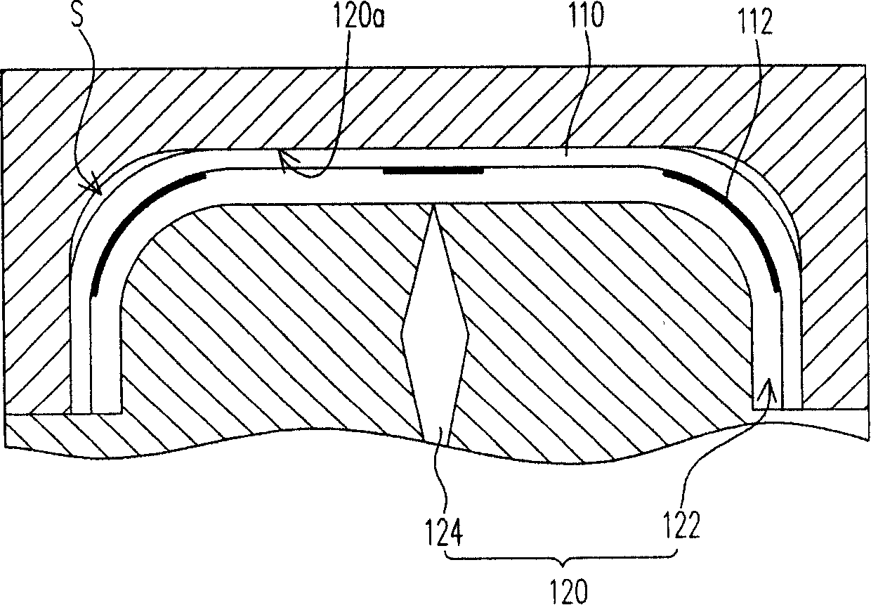
[0017] figure 2 It is a flow chart of an in-mold decoration printing method in a preferred embodiment of the present invention. Please refer to figure 2 , The in-mold decoration printing method of this embodiment includes the following steps. First, step S1 is performed to provide a patterned film and a mold, wherein the patterned film has a preset pattern, and the mold has a mold cavity, a plurality of air inlets, and a sprue, wherein the air inlet and the sprue communicate with the mold cavity, and The patterned film is arranged on the inner wall of the mould.

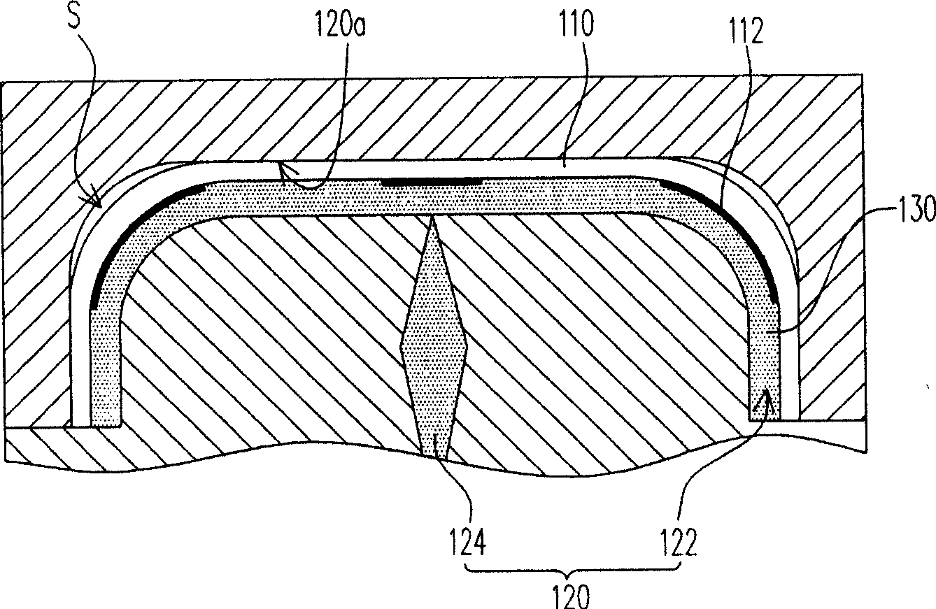
[0018] Next, step S2 is performed to inject plastic into the mold cavity from the pouring port. Afterwards, step S3 is performed, introducing airflow from the air inlet, so that the plastic is...


PUM


Abstract

The invention relates to an in-die decoration printing method, which comprises the following steps. Firstly, a pattern thin film and a die assembly are provided, the pattern thin film is provided with a presetting pattern, the die assembly is provided with a die cavity, a plurality of air inlets and a pouring hole, wherein, the air inlets and the pouring hole are communicated with the die cavity, and the pattern thin film is arranged on the wall of the die assembly. In succession, the plastic self pouring hole is injected in the die cavity. Later, air flow is fetched in from the air inlet, to lead plastic to being extruded to the pattern thin film by the air flow, and lead the pattern thin film to being attached on the inner wall of the die assembly flatly.

Description

technical field [0001] The present invention relates to a printing method, and in particular to an in-mold decoration (InMold Decoration, IMD) printing method. Background technique [0002] Generally speaking, the in-mold decoration printing method is applied to the decoration processing of plastic casings. For example, the patterned plastic case of a mobile phone is a product produced by the in-mold decoration printing method. Please refer to Figure 1A to Figure 1C , Figure 1A to Figure 1C It is a process sectional view of a known in-mold decoration printing method. The in-mold decoration printing method of known technology comprises the following steps: at first, as Figure 1A As shown, a patterned film 110 is disposed on an inner wall 120 a of a mold 120 , wherein the patterned film 110 has an ink pattern 112 . Next, if Figure 1B As shown, the plastic 130 is injected from a sprue 124 of the mold 120 such that the plastic 130 fills the mold cavity 122 . After the p...

Claims


Application Information

Patent Timeline
IPC IPC(8): B29C45/14B29C45/57
Inventor 张木财郑定群康兆锋
Owner ASUSTEK COMPUTER INC
Why Eureka
Try Eureka