
Button keyhole sewing machine

A sewing machine and button technology, which is applied to sewing machine components, thread hooks for sewing machines, and ferrule mechanisms for sewing machines, etc., can solve problems such as complicated threading operations.

Inactive Publication Date: 2008-05-07
JUKI CORP
View PDF1 Cites 4 Cited by
  • Summary
  • Abstract
  • Description
  • Claims
  • Application Information

AI Technical Summary

Problems solved by technology

However, since the inside of the needle bar and looper is narrow, it is difficult to thread the needle by inserting it directly, and the threading work is very complicated.

Method used


Image

  • Button keyhole sewing machine
  • Button keyhole sewing machine
  • Button keyhole sewing machine

Examples


Embodiment Construction

[0045] (Overall structure of the embodiment)

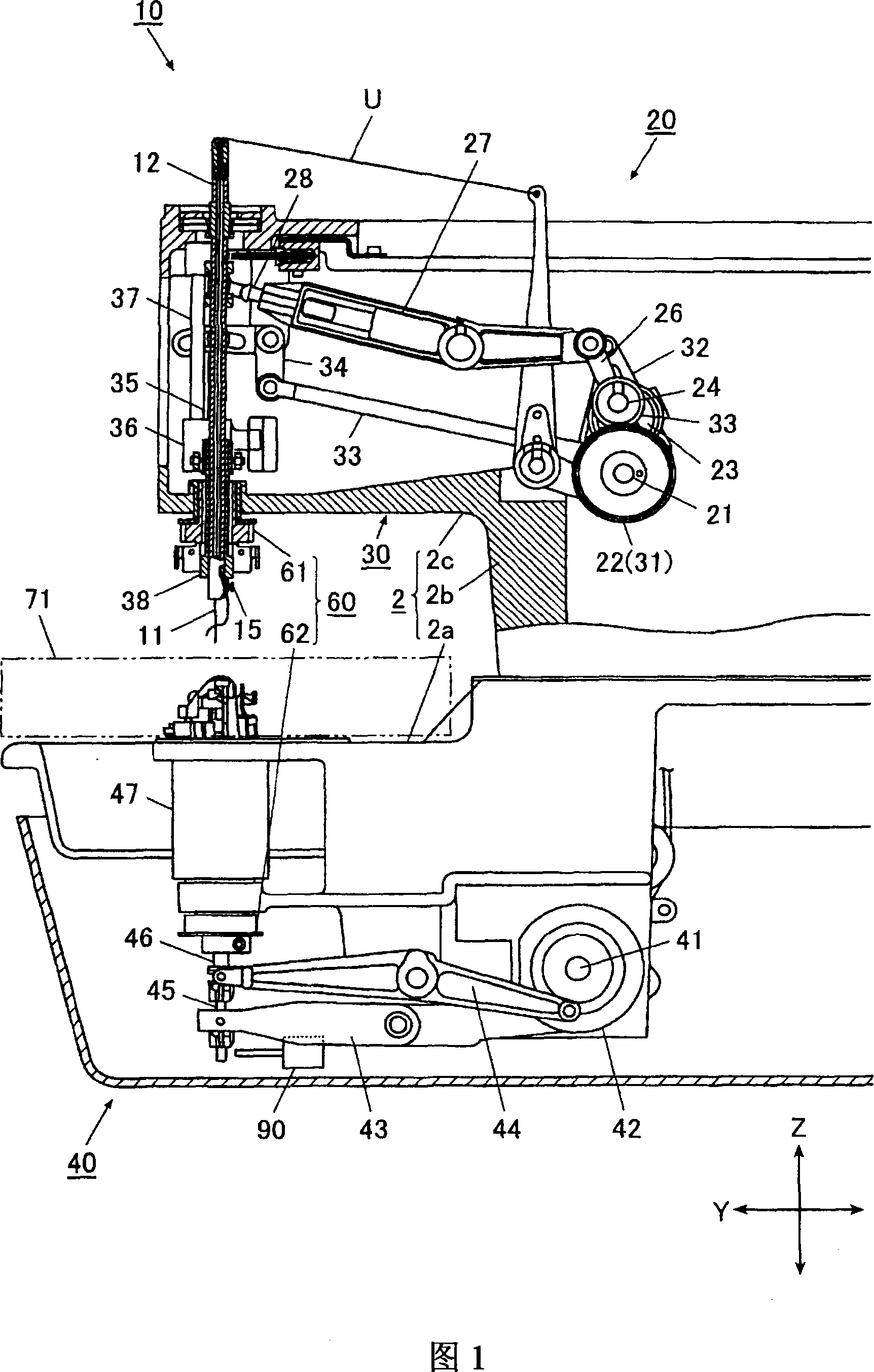
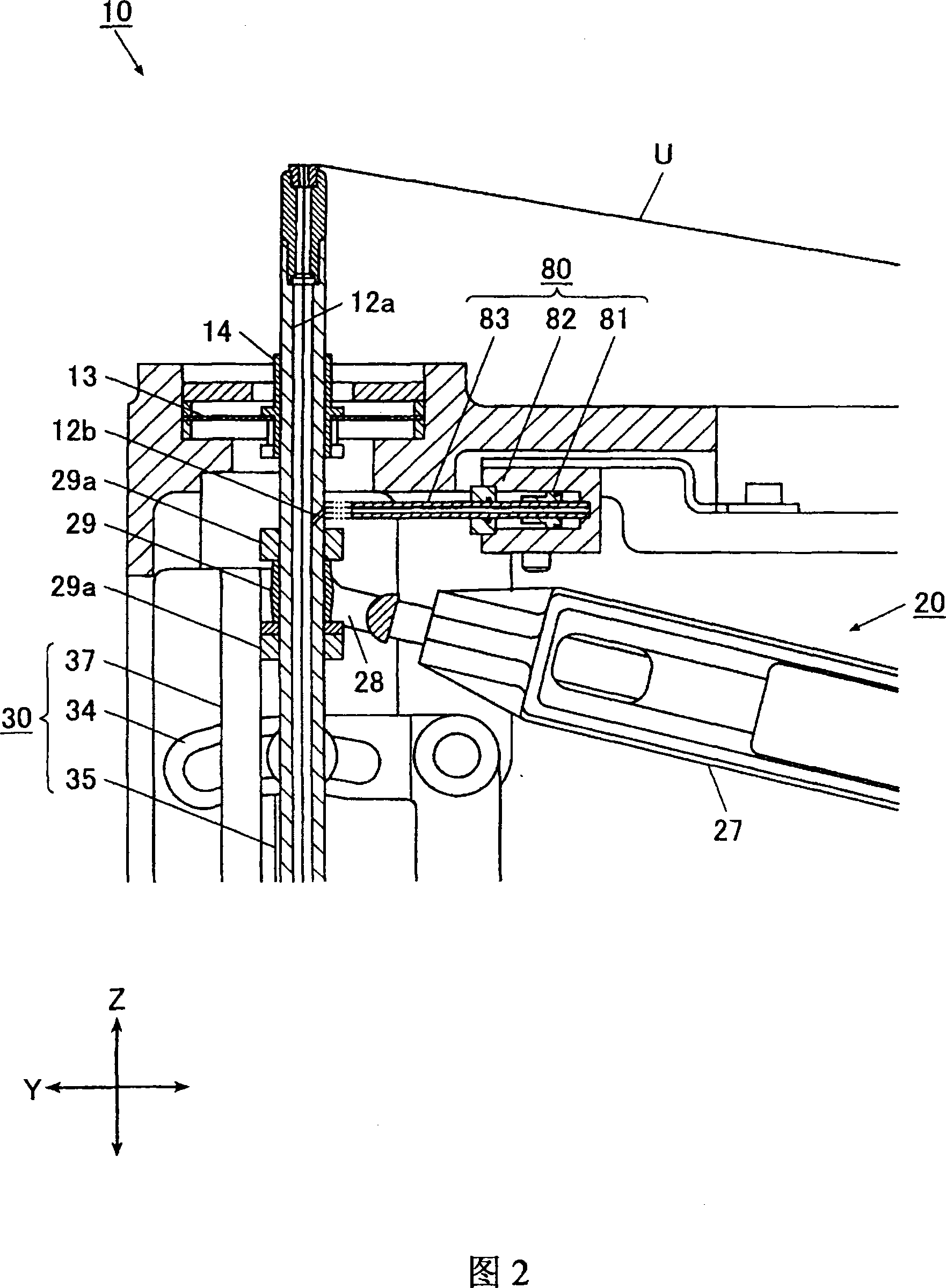
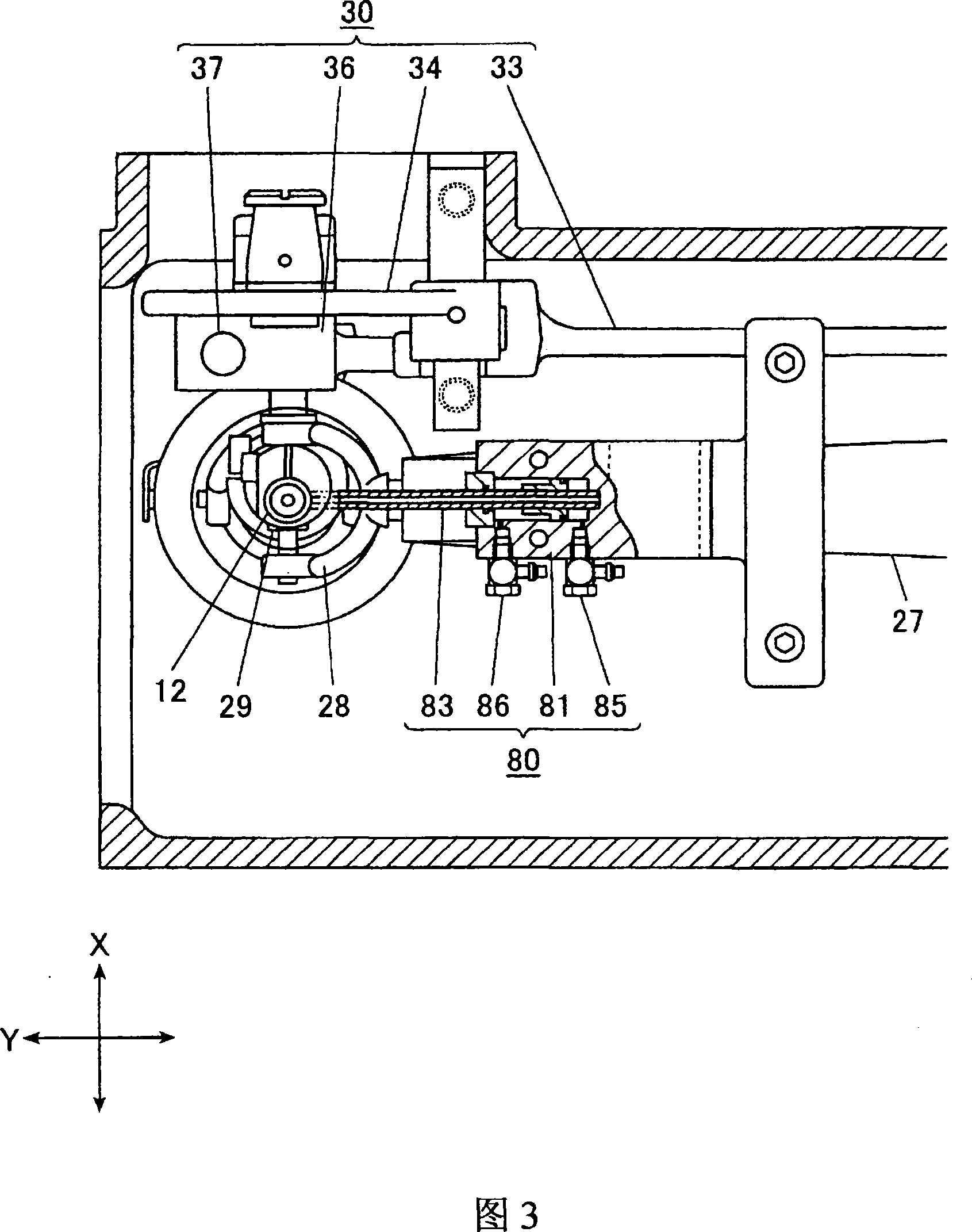
[0046] The buttonhole sewing machine 10 according to the embodiment of the present invention will be described based on FIGS. 1 to 10. 1 is a side sectional view of the buttonhole sewing machine 10, FIG. 2 is an enlarged sectional view showing the upper periphery of the needle bar 12, and FIG. 3 is an enlarged sectional view showing the upper periphery of the needle bar 12 viewed from above.

[0047] As shown in Figure 1, the buttonhole sewing machine 10 has: a base portion 2a, which is located at the lower part of the sewing machine as a whole, and has a substantially rectangular box shape; a longitudinal body portion 2b, which is provided on one end of the base portion 2a; And the arm portion 2c is provided to extend from the longitudinal body portion 2b and the base portion 2a in the same direction. Here, in the following description, the direction in which the longitudinal body portion 2b is erected is set to the Z-axis direction,...


PUM


Abstract

According to the invention, the needle thread can be pulled through eyelet simply. The sewing machine of the invention is provided with a needle bar (12) having a thread guiding part (12a) passing through upper end to the lower end; a vertical motion mechanism (20) of needle bar; a needle-swinging mechanism (30) which enables the needle bar to swing; a looper mechanism (40); a turning mechanism (60) which enables the needle bar and looper mechanism base to rotate; and a motion mechanism which enables the process cloth to move, and forms an inclined needle-bar opening (12b) at the needle bar for blowing of air into needle thread eyelet. Also is provided with an air nozzle for feeding thread mounted on the side of the needle bar; and a controller for controlling the vertical motion mechanism, needle-swinging mechanism and rotation mechanism, which enables the needle-bar opening to align with the air jet hole of the air nozzle.

Description

Technical field [0001] The invention relates to a buttonhole sewing machine for threading upper thread or lower thread. Background technique [0002] In the conventional buttonhole sewing machine, the pull-out hole of the needle bar from its upper end to the vicinity of the lower end is formed into a hollow as a suture passage, and the upper thread passing through the balance is further guided through the hollow interior of the needle bar. To the stitches. [0003] In addition, the above-mentioned conventional buttonhole sewing machine has: a hollow tubular looper drive shaft, which is arranged at the center of the looper base supporting the looper and the spreader; and the wire puller drive Shaft, which is inserted into the inner side of the drive shaft of the ringing device. The above-mentioned drive shaft can move up and down with respect to the base of the looping device, and by each reciprocating up and down movement, the looping device and the wire puller can respectively p...

Claims


Application Information

Patent Timeline
IPC IPC(8): D05B3/06D05B53/00D05B61/00D05B63/00
CPCD05B3/06D05D2207/04D05B87/00
Inventor 村井健二
Owner JUKI CORP
Learn More