Cloth pressing pin drive structure of sewing machine

A technology for presser feet and sewing machines, applied in the field of sewing machines, can solve the problems of affecting the service life and abnormal wear of the push rod, and achieve the effect of improving the service life and avoiding abnormal wear and tear.

Inactive Publication Date: 2008-05-07
MING JANG SEWING MACHINE
View PDF0 Cites 2 Cited by
  • Summary
  • Abstract
  • Description
  • Claims
  • Application Information

AI Technical Summary

Problems solved by technology

[0004] However, even if the actuator's push rod and the link group are in vertical contact at the maximum thrust, since the actuator's push rod and the link group are directly pushed between the beginning and the end of the time when the actuator's push rod directly pushes the link group, the actuator's push rod and the linkage There will be relative sliding displacement between the rod groups as the height of the presser foot lifting foot changes, and the lateral force such as frictional resistance caused by sliding friction acts on the push rod, so the actuator push rod may still be abnormally biased to one side wear, thereby affecting its service life

Method used


Image

  • Cloth pressing pin drive structure of sewing machine
  • Cloth pressing pin drive structure of sewing machine
  • Cloth pressing pin drive structure of sewing machine

Examples


Embodiment Construction

[0019] The driving structure of the presser foot of the sewing machine of the present invention will be described below.

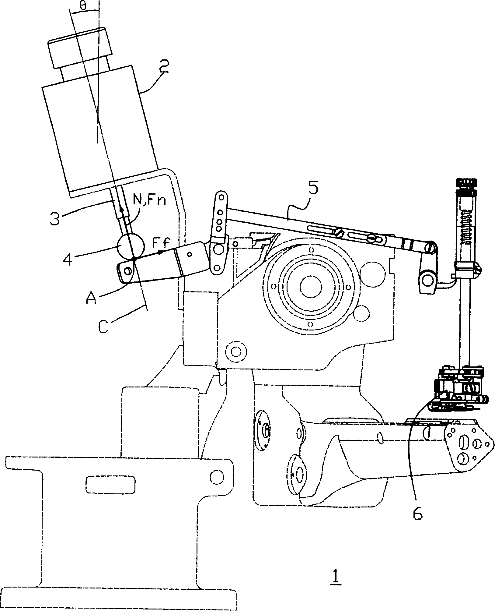
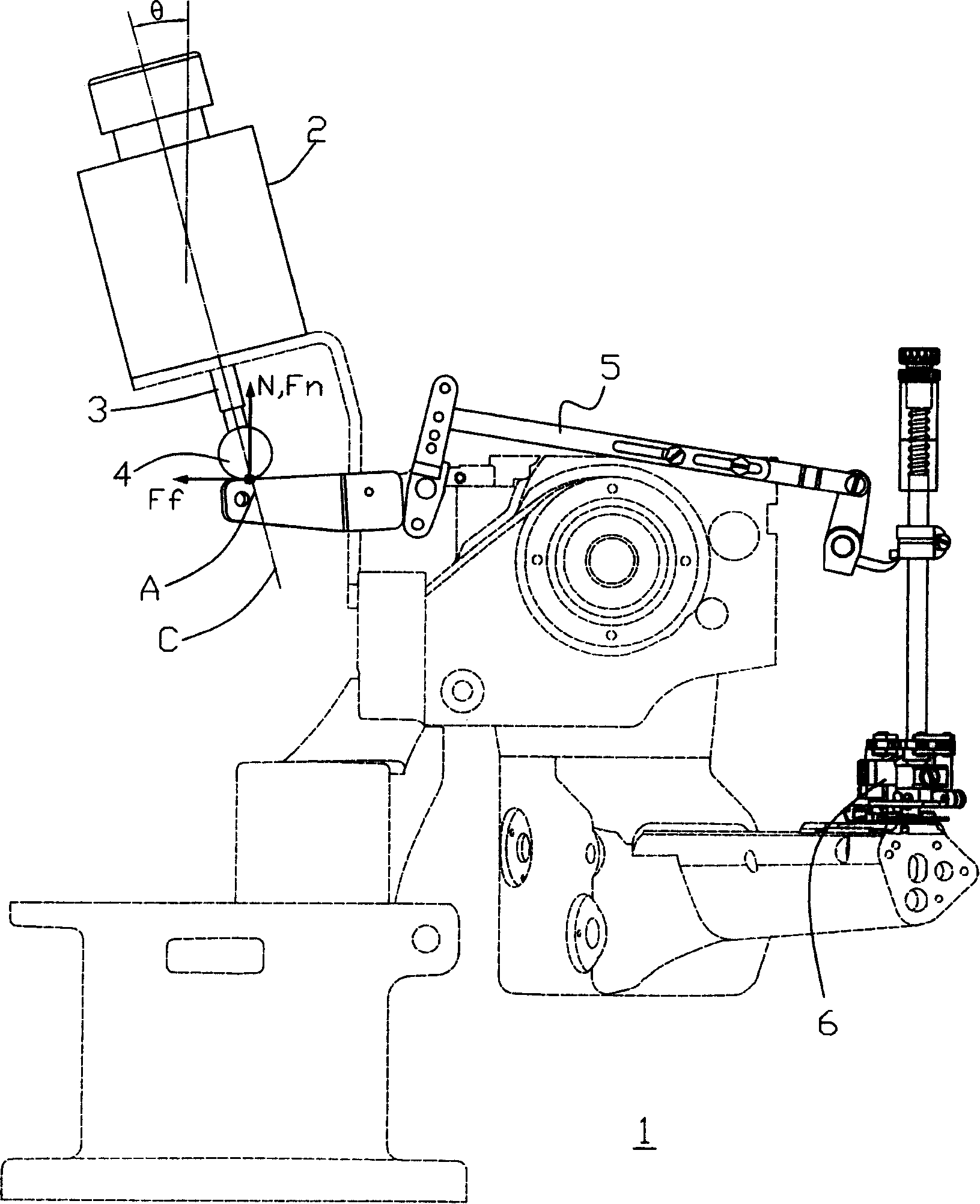
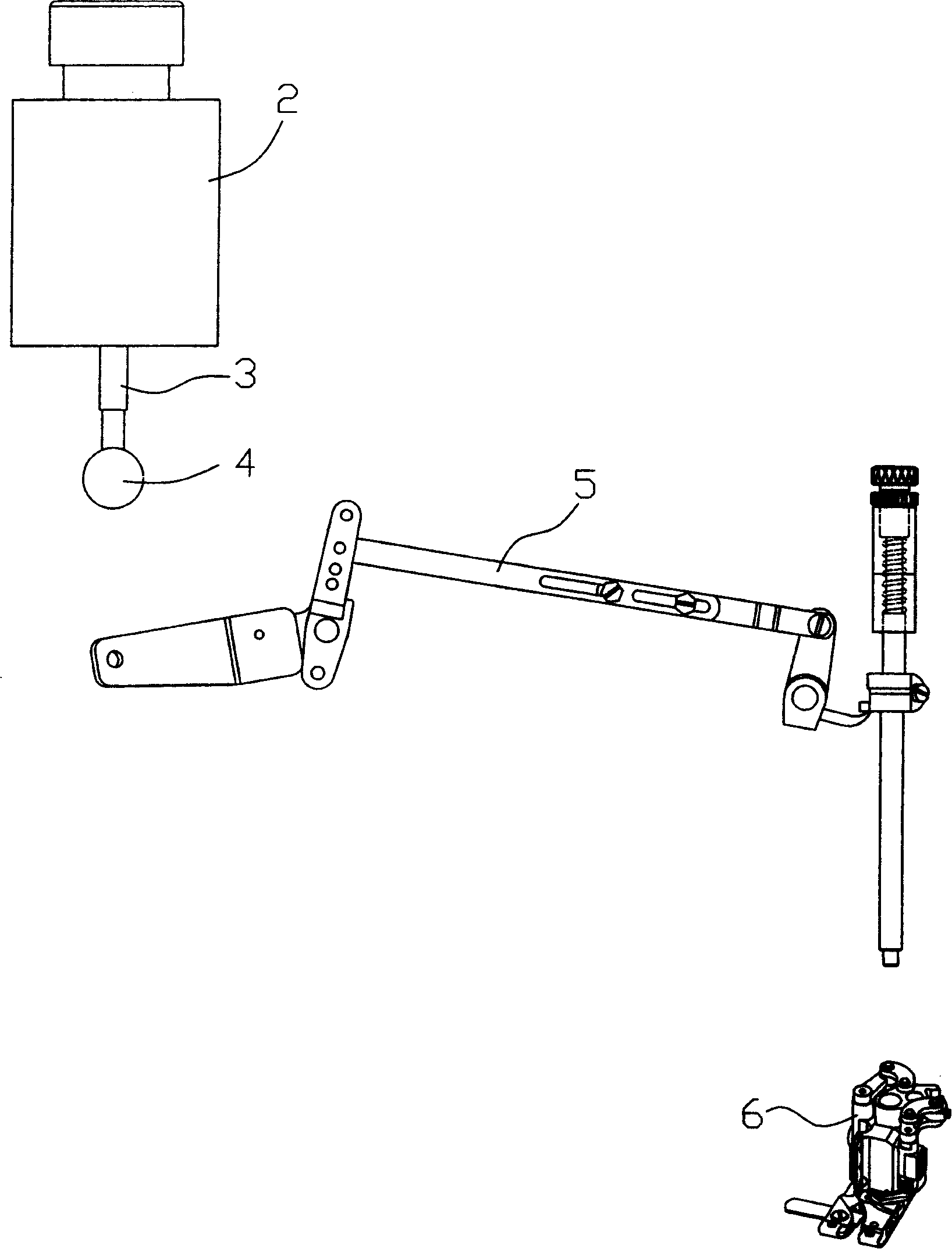
[0020] figure 1 In the first embodiment of the cloth presser foot drive structure of the sewing machine of the present invention, the cloth presser foot is a schematic diagram of the state where the cloth presser foot is located at the highest position of the lifting foot; figure 2 It is a schematic diagram of the state where the presser foot is at the presser position in the same embodiment; image 3 In an exploded view, the components illustrated in this embodiment can be clearly shown. As shown in the figure, a link group 5 for driving the cloth presser foot 6 is provided in the sewing machine 1, so that the cloth presser foot 6 of the linkage group 5 generates a cloth presser or lifter action. In this embodiment, the axial direction of the actuator 2 and the vertical reference line form an inclination angle θ, the push rod 3 in the actuator 2 can telesc...


PUM


Abstract

The invention discloses a drive structure of cloth pressing foot for a sewing machine, which is characterized in that: a push rod of an actuator does not directly push a linkage but pushes through a roller; friction can be avoided due to sliding through the rolling of the roller even if relative displacement of the push rod for the actuator opposing to the contact point of the linkage is produced between the starting and the ending of driving, thereby avoiding lateral force due to the friction between the push rod of the actuator and the linkage; when the cloth pressing foot is lifted to the highest point, the roller is propped against normal line of the contact surface on the contact point of the linkage and coincides at the axial extending line of the push rod; the contact point between the linkage and the roller is arranged at the axial extending line of the push rod for the actuator; eccentric force can be avoided upon the push rod, thereby avoiding abnormal abrasion that the push rod leans toward one side.

Description

Technical field [0001] The invention relates to a sewing machine, in particular to a cloth presser driving structure of the sewing machine. Background technique [0002] The known sewing machine presser foot drive structure uses an actuator to directly push the linkage group, and the linkage group drives the cloth presser foot to lift the foot upward. For example, it is disclosed in Taiwan New Patent Publication No. 443338. [0003] The above-mentioned announcement uses the design of the actuator to directly push the connecting rod group. When the actuator directly drives the connecting rod group, it may cause the push rod of the actuator to bear the eccentric reaction force, which may cause abnormal wear to one side. Therefore, an improved solution is proposed to set an inclined actuator installation angle so that the push rod of the actuator is connected to the push rod at the highest thrust, that is, at the highest point of the presser foot. The rod groups are in vertical cont...

Claims


Application Information

Patent Timeline
Patent Type & Authority Applications(China)
IPC IPC(8): D05B29/06D05B29/12
Inventor 廖金旺林春祥
Owner MING JANG SEWING MACHINE
Why Eureka
Try Eureka