Electroacoustic transducer

An electro-acoustic conversion and fixed position technology, applied in the direction of electrical components, sensors, etc., can solve the problem of residual sound pressure reduction and achieve the effect of thinning and sufficient sound pressure

Inactive Publication Date: 2008-05-07
SANYO ELECTRIC CO LTD
View PDF1 Cites 3 Cited by
  • Summary
  • Abstract
  • Description
  • Claims
  • Application Information

AI Technical Summary

Problems solved by technology

[0019] However, in the thin speaker shown in FIG. 35, only the magnetic flux component in the direction perpendicular to the axis of the coil in the magnetic flux generated from the magnet acts as a driving force for the coil, and the component in the direction perpendicular to the axis of the coil acts as a driving force for the coil. Parallel magnetic flux components do not contribute to the driving force of the coil, so there remains the problem of a large influence on sound pressure reduction due to miniaturization / thinning

Method used


Image

  • Electroacoustic transducer
  • Electroacoustic transducer
  • Electroacoustic transducer

Examples


no. 1 example

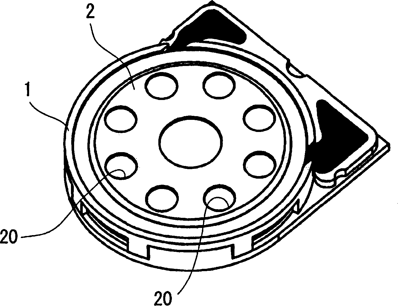
[0073] Such as figure 1 and figure 2 As shown, the electroacoustic transducer of the first embodiment related to the present invention is provided with a flat cylindrical frame 1, and a disc-shaped cover having a plurality of sound emitting holes 20 is mounted on the front opening of the frame 1. 2.

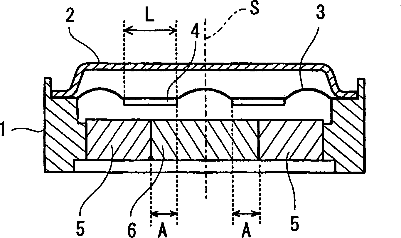
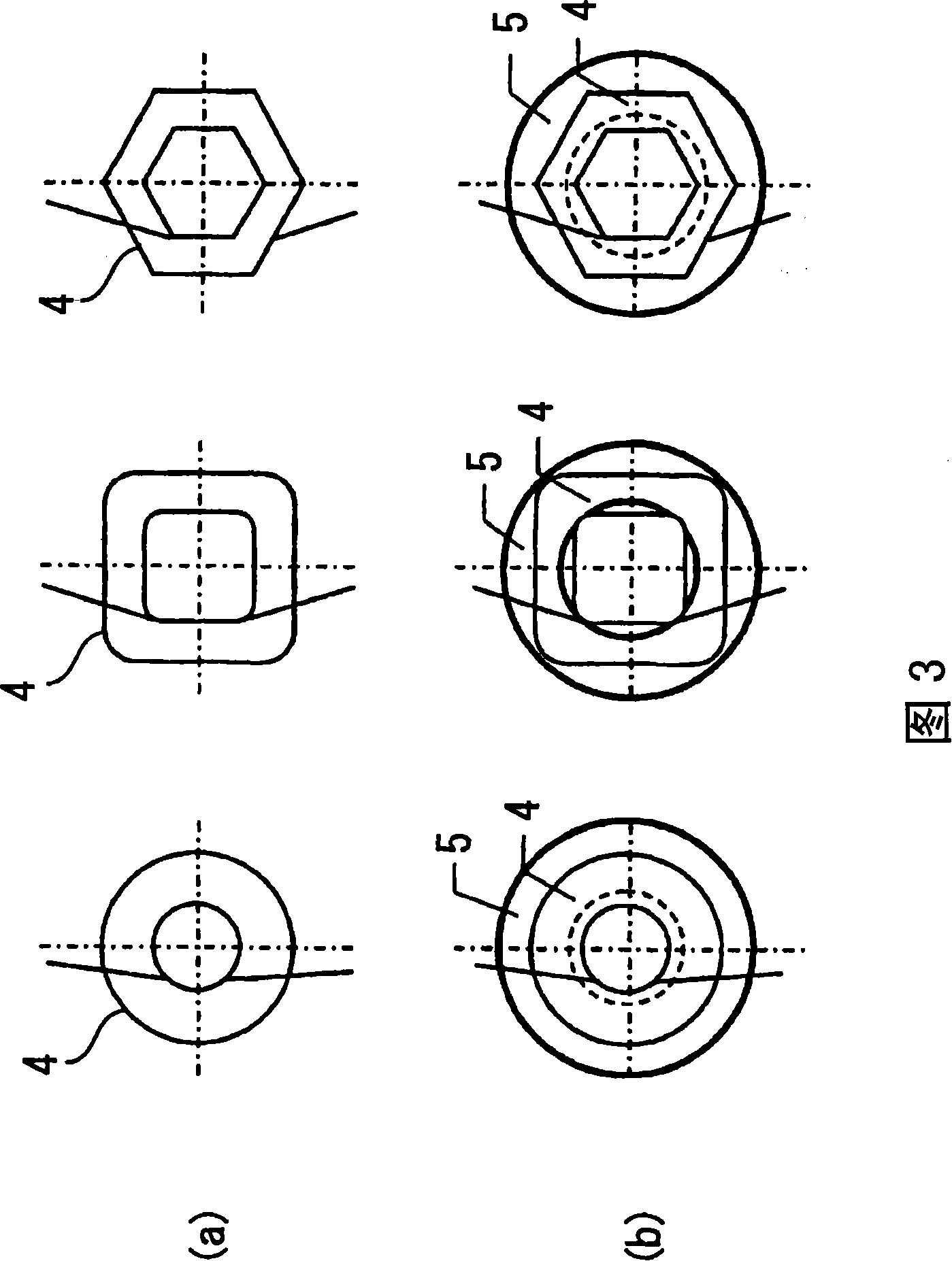
[0074] Such as figure 2 As shown, a disk-shaped vibrating plate 3 is provided inside the frame 1 , and the outer peripheral portion of the vibrating plate 3 is sandwiched between the frame 1 and the cover 2 . A flat cross-sectional coil 4 wound around the axis S on the vibration plate 3 is fixed to the back surface of the vibration plate 3 .

[0075] In addition, inside the frame 1, a predetermined gap is provided between the coil 4 and an annular outer magnet (outer magnet) 5 is fixed, and the central hole of the outer magnet 5 is equipped with a metal ring made of iron, permalloy (permalloy) or the like. A disk-shaped inner core (inner core) 6 formed of a ferromagnetic m...

no. 2 example

[0088] Such as Figure 6 Shown in (a), the electroacoustic transducer of the second embodiment related to the present invention, except that the central hole of the outer magnet 5 is equipped with a cylindrical inner magnet 51, other structures are the same as those of the electroacoustic transducer of the first embodiment same.

[0089] Inner magnet 51 such as Figure 6 As shown in (a), it is magnetized in the direction opposite to the outer magnet 5, and the lines of magnetic force emitted from the outer magnet 5 and the inner magnet 51 are as follows: Figure 12 As shown in (a), a loop is drawn on the inner peripheral surface side and the outer peripheral surface side of the outer magnet 5 , and the magnetic flux loop on the inner peripheral surface side acts on the coil 4 .

[0090] Here, since the inner magnet 51 having a polarity opposite to that of the outer magnet 5 is arranged in the central hole of the outer magnet 5, the magnetic flux loop on the inner peripheral su...

no. 3 example

[0102] Such as Figure 16 and Figure 17 As shown, the electroacoustic transducing device of the third embodiment related to the present invention is provided with a flat cylindrical frame 11 having an oblong or elliptical planar shape, and a plurality of sound emitting holes 20 are mounted on the front opening of the frame 11. A cover 21 having an oblong or elliptical planar shape.

[0103] Such as Figure 17 As shown, a vibrating plate 31 having an oblong or elliptical planar shape is provided inside the frame 11 , and the outer peripheral portion of the vibrating plate 31 is sandwiched between the frame 11 and the cover 21 . A flat cross-sectional coil 41 wound around the axis S on the vibration plate 31 is fixed to the back surface of the vibration plate 31 .

[0104] In addition, a pair of rectangular parallelepiped outer magnets 7, 7 are fixed with a prescribed gap between the frame 11 and the coil 41, and a strong magnet made of iron, permalloy, etc. is installed bet...


PUM


Abstract

An electroacoustic transducer of the present invention includes a diaphragm 3 having a periphery as a fixed end, a coil 4 having an axis perpendicular to the diaphragm 3 and attached centrally to the diaphragm 3 , and a direct current magnetic field generator fixed in position as spaced apart from the coil 4 by a gap provided axially of the coil 4 . The diaphragm 3 is driven by applying to the coil 4 a magnetic flux emitted from a surface of the direct current magnetic field generator that faces the coil 4 . The direct current magnetic field generator includes a ring-shaped outer magnet 5 located coaxially with the axis of the coil 4 and magnetized in the direction parallel to the axis, and an inner core 6 including a ferromagnet and located in the central hole of the outer magnet 5.

Description

technical field [0001] The present invention relates to an electroacoustic transducer that converts an electric signal into sound, such as a speaker, and particularly relates to an electroacoustic transducer having a structure effective for thinning. Background technique [0002] The speaker supplies a drive current to a coil attached to the diaphragm, and applies magnetic flux radiated from a DC magnetic field generator including a magnet to the coil to vibrate the diaphragm. [0003] For example, in Figure 31 In the shown conventional external magnetic speaker, the coil 9 is wound into a cylindrical shape, and a ring-shaped magnet 90 is arranged outside the coil 9, and a cylindrical magnetic pole (pole) 95 is arranged inside. , and a top plate (upper plate) 97 is mounted on the surface of the magnet 90 , and a bottom plate (bottom plate) 96 is mounted on the magnetic pole 95 and the back surface of the magnet 90 . [0004] In this speaker, the coil 9 is driven by being a...

Claims


Application Information

Patent Timeline
Patent Type & Authority Applications(China)
IPC IPC(8): H04R9/02H04R9/06
CPCH04R9/047H04R9/025
Inventor 畠中有纪小须田和之
Owner SANYO ELECTRIC CO LTD
Why Eureka
Try Eureka