Chamber filter plate

A technology of filter plates and filter presses, applied in the direction of filtration separation, separation methods, chemical instruments and methods, etc., can solve problems such as deformation, and achieve the effect of uniform force distribution

Inactive Publication Date: 2011-06-15
JVK FILTRATION SYST
View PDF1 Cites 0 Cited by
  • Summary
  • Abstract
  • Description
  • Claims
  • Application Information

AI Technical Summary

Problems solved by technology

There is therefore the risk that the plate body is deformed in an undesired manner due to the high filter pressure

Method used


Image

  • Chamber filter plate
  • Chamber filter plate
  • Chamber filter plate

Examples


Embodiment Construction

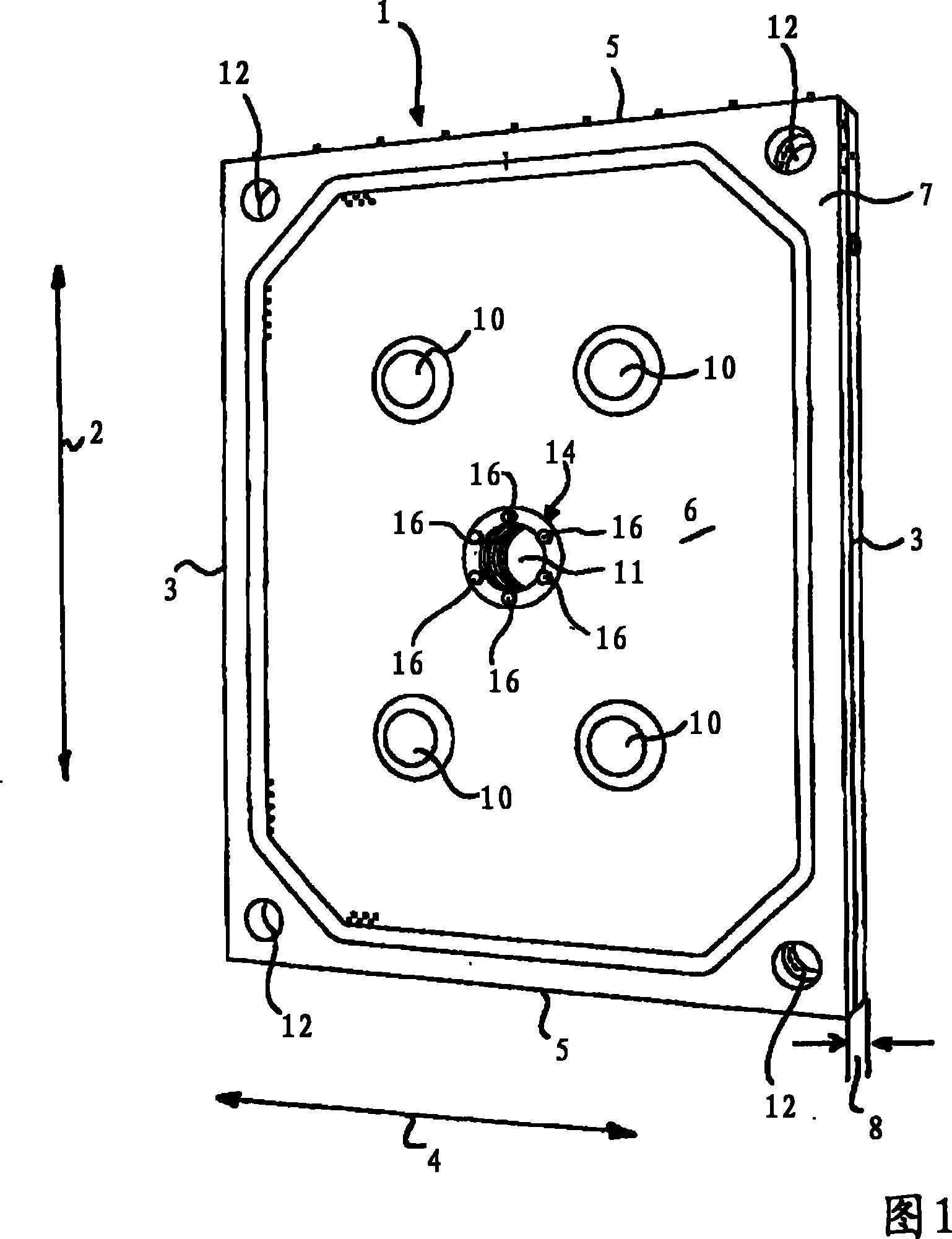
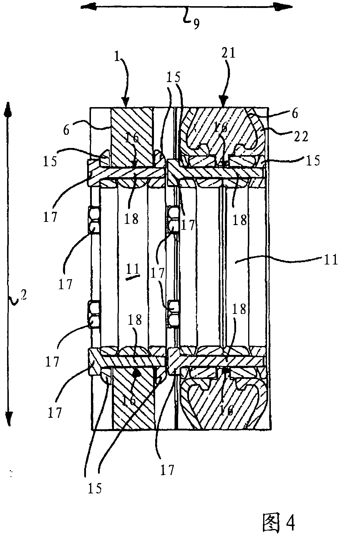
[0018] The rectangular box filter plate 1 has two longitudinal sides 3 running parallel in the longitudinal direction 2 and two likewise parallel transverse sides 5 running perpendicularly to the longitudinal sides 3 in the transverse direction 4 . The plate body of the chamber filter plate 1 is formed by a plate surface 6 and a plate edge 7 surrounding the plate surface 6 . The plate edge 7 extending around the plate surface 6 has a thickness 8 which is greater than the thickness of the plate body in the region of the plate surface 6 . This means that the plate surface 6 is set back relative to the plate edge 7 in the plate alignment direction 9 ( FIG. 3 ), which extends perpendicularly to the longitudinal direction 2 and the transverse direction 4 . In this way the plate edge 7 provides a filter tank which is open on one side, with the plate surface 6 as the filter tank bottom.

[0019] In the exemplary embodiment, four supports 10 protruding from the plate surface 6 in the...


PUM


Abstract

The invention relates to a chamber filter plate (1) for a filter press, comprising a plate edge (7) which is thicker than the surface (6) of the plate and surrounds the same. Said plate edge comprises at least one prefilt supply borehole (11) in the surface (6) of the plate, and a supporting ring (14) surrounding the edge of the prefilt supply borehole (11). An assembly flange (15) of the supporting ring (14) extends in the same plane as the surface (6) of the plate, and a projecting element projects from the assembly flange (15).

Description

technical field [0001] The invention relates to a box-type filter plate used for a filter press. Chamber filter plates of this type consist of a plate body and a plate edge which is thickened relative to the plate surface of the plate body and runs around. The edge of the plate therefore has a greater thickness than the body of the plate, so that a recess is formed inside the edge of the plate. If two or more chamber filter plates are arranged next to each other, their edges rest against each other and form a filter cell within the respective edges. Background technique [0002] In order to feed the mud to be filtered into the filter tank, at least one mud inlet is arranged in the plate body. The mud inlet usually has a support ring surrounding its edge. [0003] The side-by-side filter chamber plates for forming the filter plate pack abut one another with their edge regions and are thus supported relative to each other. The plate bodies within the edge of the plate init...

Claims


Application Information

Patent Timeline
Patent Type & Authority Patents(China)
IPC IPC(8): B01D25/21
CPCB01D25/215B01D25/285B01D25/12
Inventor M·赫尔曼B·扎尔鲍姆
Owner JVK FILTRATION SYST
Why Eureka
Try Eureka