
Device for housing and connection of accessories for switches

A technology for connecting devices and accessories, which is applied to parts of protection switches, electrical switches, switches whose voltage is lower than a predetermined value, etc., and can solve problems such as inability to work, limited application scope, and accessory failures.

Active Publication Date: 2008-05-07
ABB (SCHWEIZ) AG
View PDF2 Cites 6 Cited by
  • Summary
  • Abstract
  • Description
  • Claims
  • Application Information

AI Technical Summary

Problems solved by technology

Therefore, this aspect limits the scope of application
If, for example, a power outage occurs in said auxiliary power supply, it will lead to the failure of each accessory, so that all accessories, including those of the passive type, will not work

Method used


Image

  • Device for housing and connection of accessories for switches
  • Device for housing and connection of accessories for switches
  • Device for housing and connection of accessories for switches

Examples


Embodiment Construction

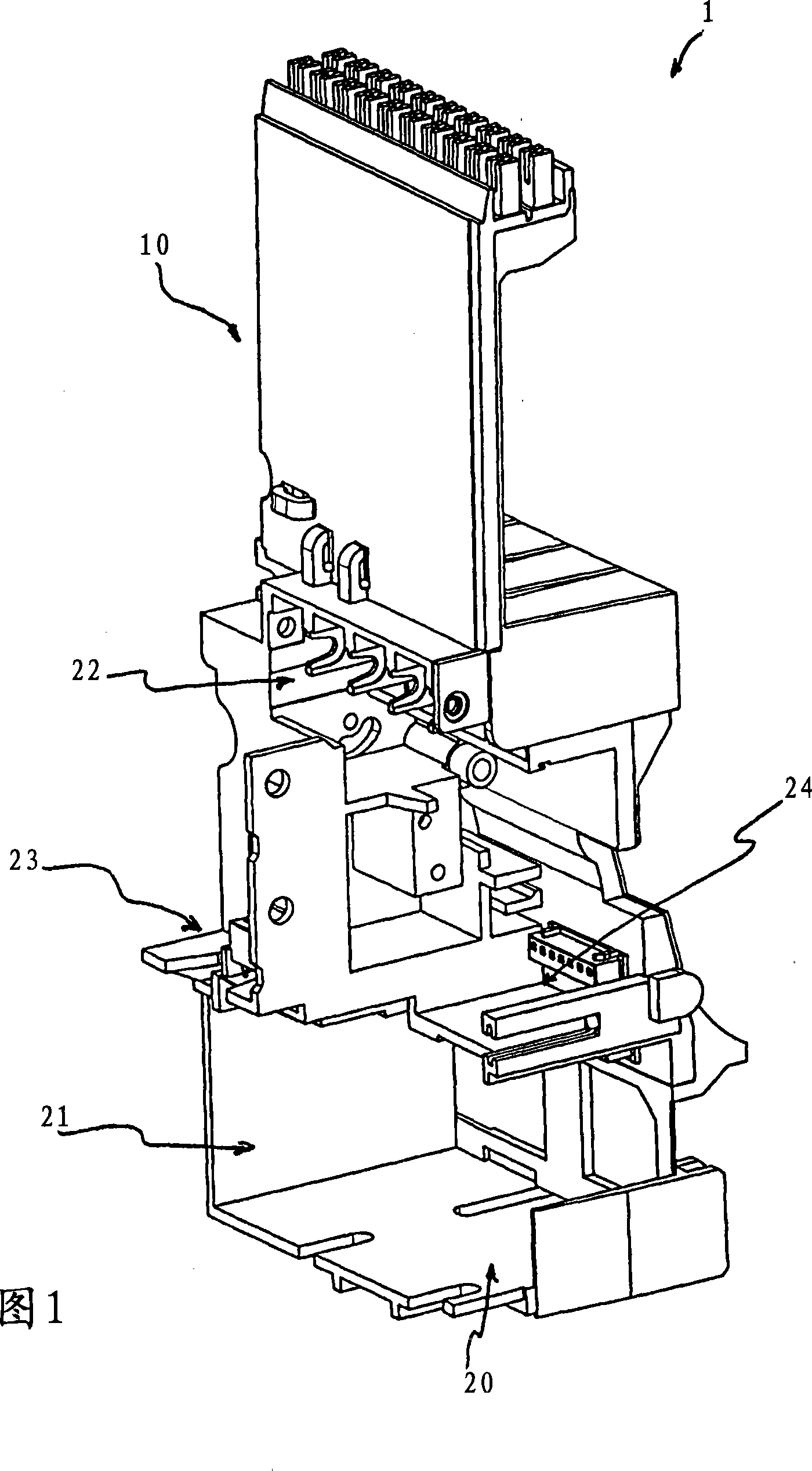
[0026] Referring to FIG. 1 , according to the invention, a device 1 for receiving and connecting low-voltage switchgear accessories comprises a shaped structure 10 . The shaped structure 10 instead comprises an integrated wiring busbar (not visible in FIG. 1 ) for the electrical connection of the accessories and one or more mounts 20 , 21 , 22 , 23 and 24 for receiving the accessories.

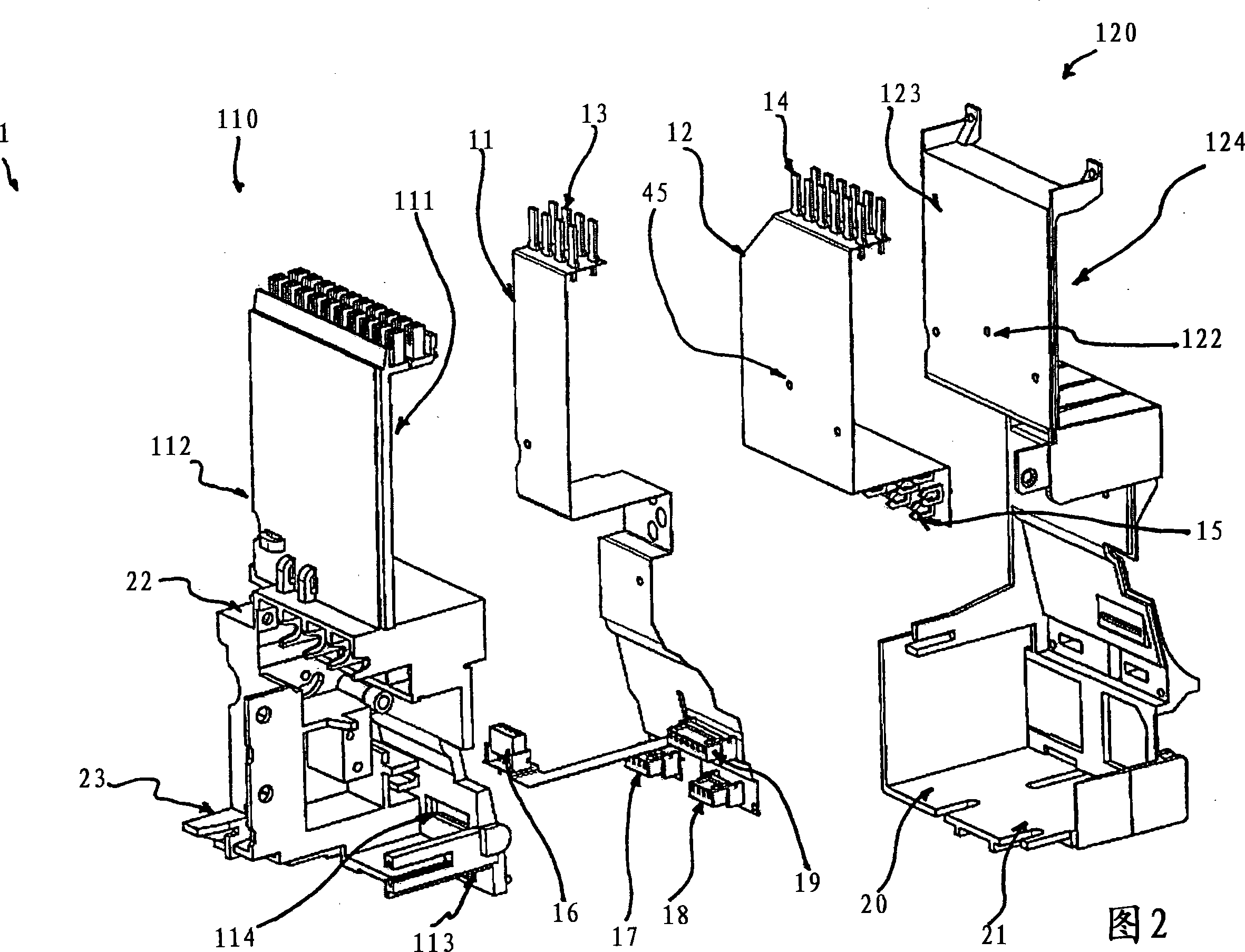
[0027] In particular, referring to FIG. 2 , the integrated wiring busbar can conveniently comprise one or more printed connection vias 11 , 12 . On these passages, at positions corresponding to appropriate points thereof, one or more terminal strips or terminals 13, 14, 15, 16, 17, 18, 19 are located for connection to said accessories or other means. In the embodiment shown in Figure 2, said terminal strips or terminals 15, 16, 17, 18, 19 are designed for connection to accessories or devices which, once said assembly is complete, are to be housed in the switch internally, while the terminals ...


PUM


Abstract

The invention relates to a device for receiving and connecting accessories, in particular for low-voltage automatic switches, said device comprising an integrated wiring support. In particular, the receiving and connecting device (1) has a shaped structure (10) comprising an integrated wiring busbar for electrical connection with said accessory. The forming structure (10) also includes one or more seats (20, 21, 22, 23, 24) for receiving said accessories.

Description

technical field [0001] The invention relates to a device for receiving and connecting accessories, in particular for low-voltage automatic switches and disconnectors, said device comprising an integrated wiring support. Background technique [0002] Low voltage automatic switches and disconnectors (ie for applications with operating voltages up to 1000V) are well known devices designed to ensure the correct functioning of specific parts of the electronic wiring system into which they are inserted, as well as the corresponding loads. Automatic switches (for example, to ensure the rated current required by different loads) can correctly connect or disconnect the load from the circuit, and realize the automatic isolation of the protected circuit. As is known, said automatic isolation takes place by galvanic isolation or breaking of specially provided contacts in case of a failure of a particular branch of the wiring system in order to obtain a complete isolation of the load wit...

Claims


Application Information

Patent Timeline
IPC IPC(8): H01H71/02H01H83/12H01H71/08H01H71/46H01H83/10
CPCH01H71/46H01H83/10H01H71/08H01H2011/0068H01H83/12H01H71/0228
Inventor S·贝萨纳A·安东尼亚齐
Owner ABB (SCHWEIZ) AG
Learn More