Filter structure of vacuum cleaner

A technology of filters and vacuum cleaners, applied in the direction of suction filters, etc., can solve problems such as unhygienic, troublesome dust removal, etc., and achieve the effects of convenient removal, improved application effect, and enhanced user reputation

Inactive Publication Date: 2008-05-14
LG ELECTRONICS (TIANJIN) APPLIANCES CO LTD
View PDF0 Cites 8 Cited by
  • Summary
  • Abstract
  • Description
  • Claims
  • Application Information

AI Technical Summary

Problems solved by technology

It can be seen that the structure of the vacuum cleaner of the above-mentioned prior art makes it very troublesome to remove dust, and th

Method used


Image

  • Filter structure of vacuum cleaner
  • Filter structure of vacuum cleaner
  • Filter structure of vacuum cleaner

Examples


Embodiment Construction

[0034] The specific embodiment of the present invention will be further described in conjunction with the accompanying drawings.

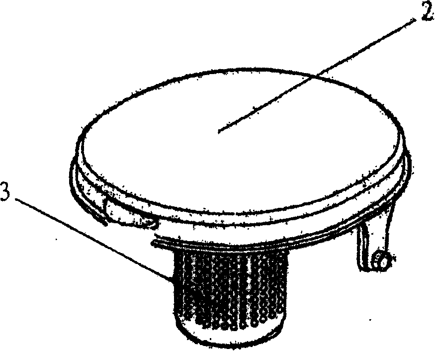
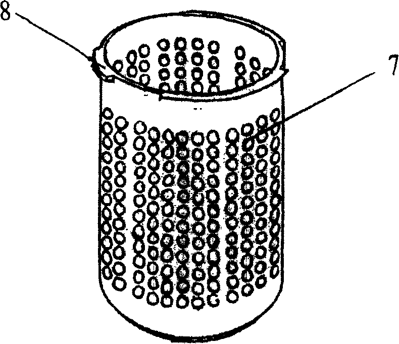
[0035] Figure 4 It is a schematic diagram of the filter involved in the present invention being fixed on the lid of the dust collecting barrel. Figure 5a It is a schematic diagram of the appearance of the filter in Fig. 3. Figure 5b It is a structural schematic diagram of the filter screen part of the filter in FIG. 3 . Figure 5c It is a structural schematic diagram of the filter element of the filter in Fig. 3 .

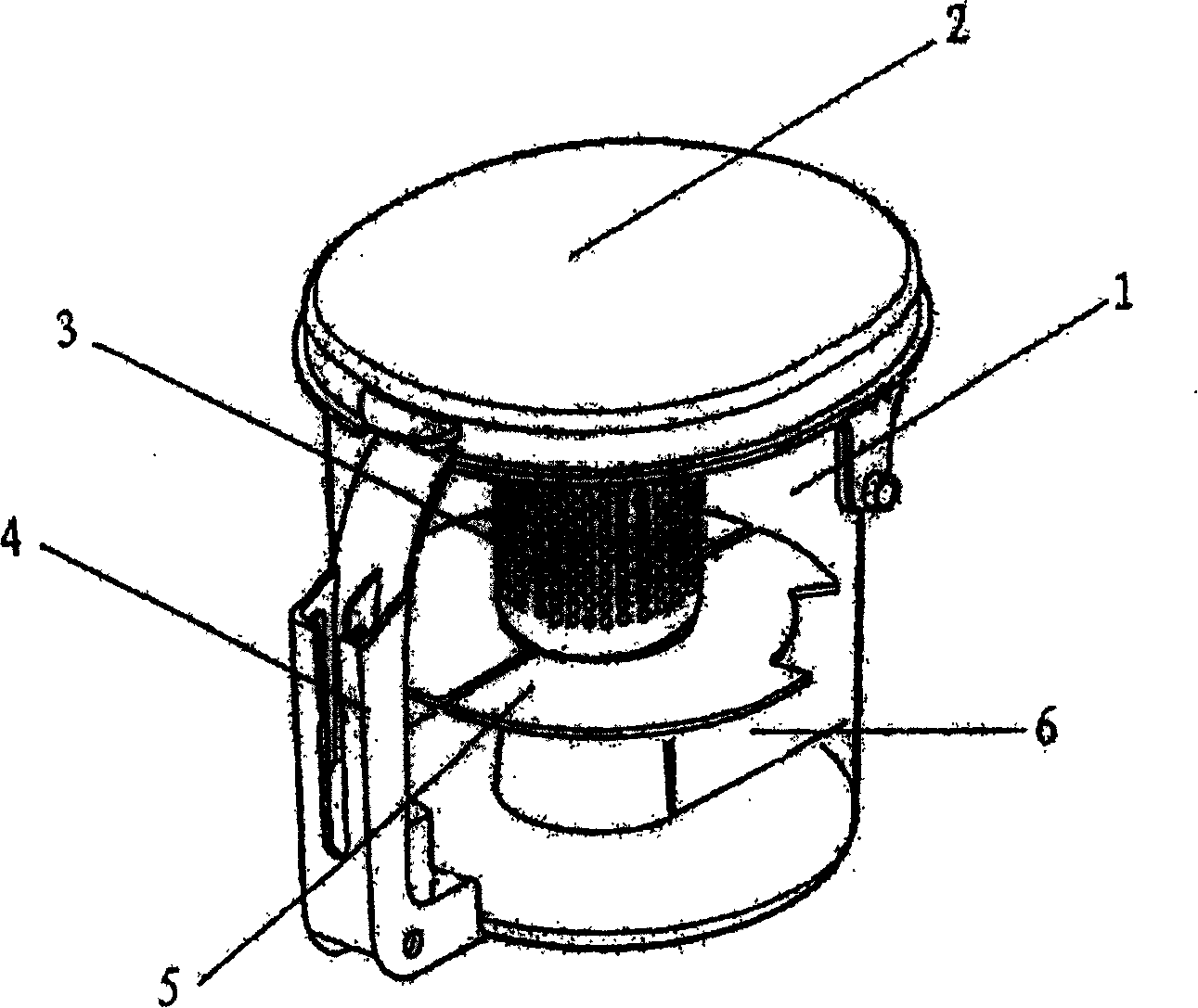
[0036] As shown in the figure, the vacuum cleaner filter structure of the present invention is composed of a filter core 90 provided with an opening mechanism on an end cover 91 and a filter screen 70 with an annular top end 71 , and the filter screen 70 is sleeved on the periphery of the filter core 90 . The filter core end cover 91 is connected together with the filter screen ring top 71 through an opening mechanism, and the out...


PUM


Abstract

The invention relates to a filter structure for the dust collector, comprising a filter cartridge and a filter screen with a circular top, wherein, an opening device is arranged on the end cover of the filter cartridge; the end cover of the filter cartridge is connected with the circular top of the filter screen through the opening device; the outer circular edge of the end cover of the filter cartridge is connected with the inner circular edge of the circular top of the filter screen; and the outer circular edge of the circular top of the filter screen is connected with the internal threads of central hole on the cover of a dust collecting barrel. The opening device arranged on the end cover of the filter cartridge comprises a fixed rib arranged on the end cover, a sliding block, which is provided with a spring and arranged in the groove of the fixed rib, and an insert, which is connected with the sliding block and can be inserted into the jack on the inner circular edge of the circular top of the filter screen; and an arc groove is arranged on each outer side of the fixed rib. The invention has the advantages that the filter dust is cleaned rapidly and conveniently; the dusty filter cartridge is prevented from being held by hand directly and unhygienicly; and the application effect of the dust collector and the customer prestige are improved.

Description

technical field [0001] The invention relates to a vacuum cleaner, in particular to a filter for a dust collecting barrel of a vacuum cleaner. Background technique [0002] The vacuum cleaner is a household appliance for indoor cleaning and hygiene, which is used to remove dust from the ground, carpets, walls, furniture and various gaps. Generally speaking, a vacuum cleaner mainly includes a suction device and a suction pipeline. The suction device mainly formed by a motor and a fan is arranged in the body. The suction pipeline includes a suction head and a suction pipe. The air port communicates with the air inlet of the fan inside the body through the telescopic pipe and flexible pipe of the suction pipe. When the vacuum cleaner is running, the motor drives the impeller of the fan to rotate at a high speed, exhausting the air in the vacuum cleaner, forming an instantaneous vacuum in the vacuum cleaner, and forming a relatively high negative pressure difference with the out...

Claims


Application Information

Patent Timeline
IPC IPC(8): A47L9/12
Inventor 李艳君
Owner LG ELECTRONICS (TIANJIN) APPLIANCES CO LTD
Why Eureka
Try Eureka