Control device for vehicle driving source
A control device and drive source technology, applied in the direction of control devices, power devices, engine control, etc., can solve problems such as acceleration, and achieve the effect of improving operability
- Summary
- Abstract
- Description
- Claims
- Application Information
AI Technical Summary
Problems solved by technology
Method used
Image

Examples
Embodiment Construction
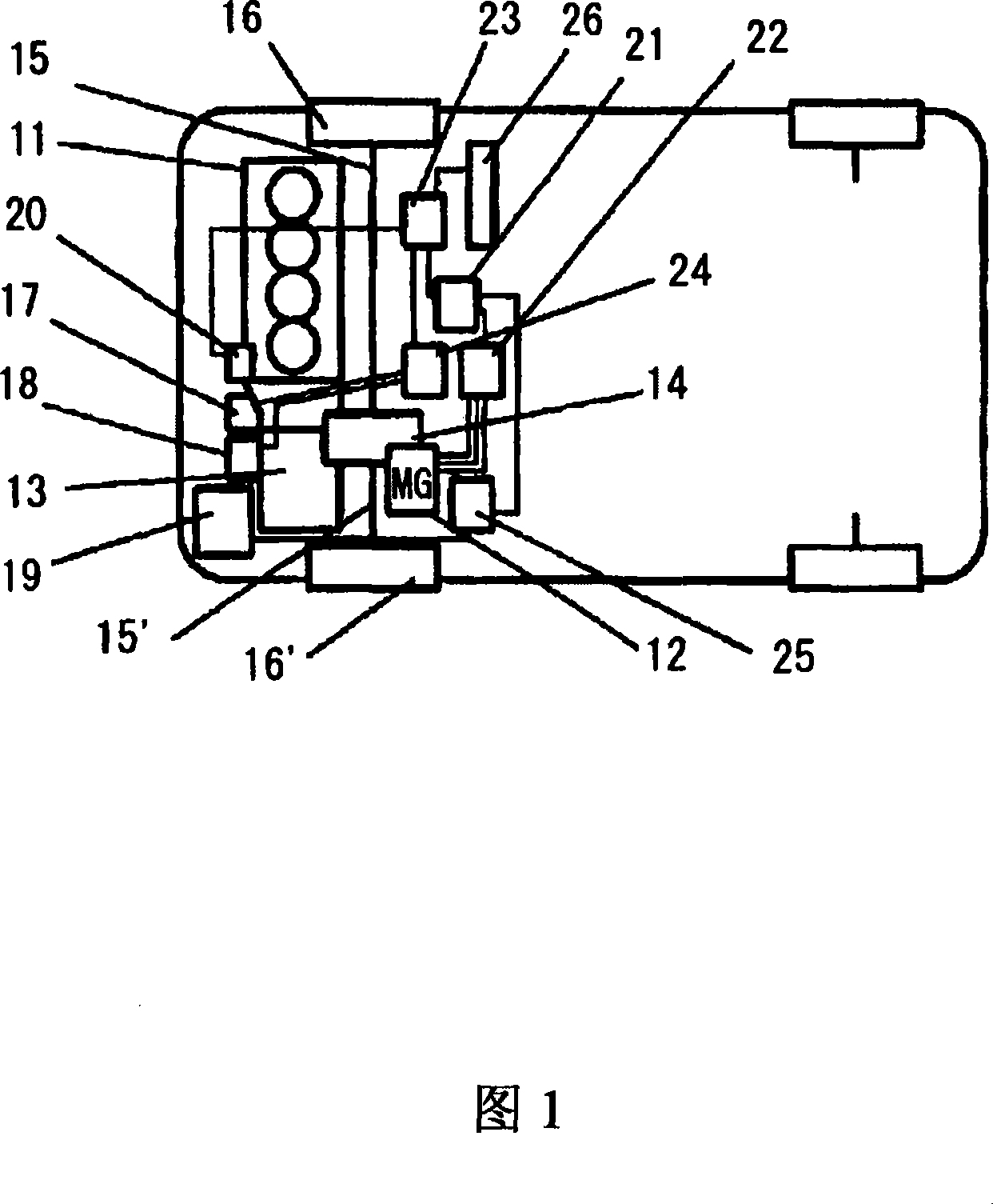
[0022] The best mode for carrying out the present invention will be described below with reference to the accompanying drawings. FIG. 1 is a diagram showing the arrangement of a hybrid vehicle to which the present invention is applied. Referring to FIG. 1, two power sources, namely an engine 11 and a motor-generator 12 are arranged in parallel to drive wheels, wherein the engine 11 (hereinafter also referred to as EG) is typically an internal combustion engine, and the motor-generator 12 (hereinafter also referred to as MG 12 ) is driven by electric power stored in the battery 19.
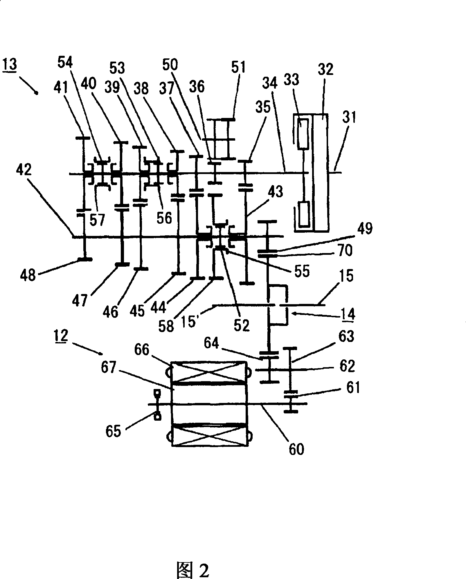
[0023] Torque output from the engine 11 is transmitted to the transmission 13 . Then, the torque is transmitted to drive shafts 15 and 15' through a differential device (differential) 14 serving as an output portion, and then to drive wheels 16 and 16' to drive the vehicle. Similarly, torque output from MG 12 is also transmitted through differential device 14 to drive shafts 15 and 15', and then ...
PUM
 Abstract
Description
Claims
Application Information
 - Generate Ideas
- Intellectual Property
- Life Sciences
- Materials
- Tech Scout
- Unparalleled Data Quality
- Higher Quality Content
- 60% Fewer Hallucinations
Browse by: Latest US Patents, China's latest patents, Technical Efficacy Thesaurus, Application Domain, Technology Topic, Popular Technical Reports.
© 2025 PatSnap. All rights reserved.Legal|Privacy policy|Modern Slavery Act Transparency Statement|Sitemap|About US| Contact US: help@patsnap.com