Dehumidifier

A technology for dehumidifiers and buckets, which is applied to household heating, lighting and heating equipment, and prevention of condensed water, etc. It can solve the problems that the drainage hose cannot be avoided and the drainage hose cannot be effectively restrained from shaking, and can be stably fixed. Effect

Inactive Publication Date: 2008-05-14
LG ELECTRONICS (TIANJIN) APPLIANCES CO LTD
View PDF0 Cites 4 Cited by
  • Summary
  • Abstract
  • Description
  • Claims
  • Application Information

AI Technical Summary

Problems solved by technology

[0005] However, the dehumidifiers in the prior art are not provided with a device for fixing the drain hose, and when the water receiving bucket is used to discharge the condensed water, the shaking of the drain hose cannot be avoided; when the drain hose is used to discharge the condensed water, it cannot be effectively Suppresses the shaking of the drain hose due to the flow of condensed water

Method used


Image

  • Dehumidifier
  • Dehumidifier
  • Dehumidifier

Examples


Embodiment Construction

[0050] Hereinafter, embodiments of the present invention will be described in detail with reference to the drawings.

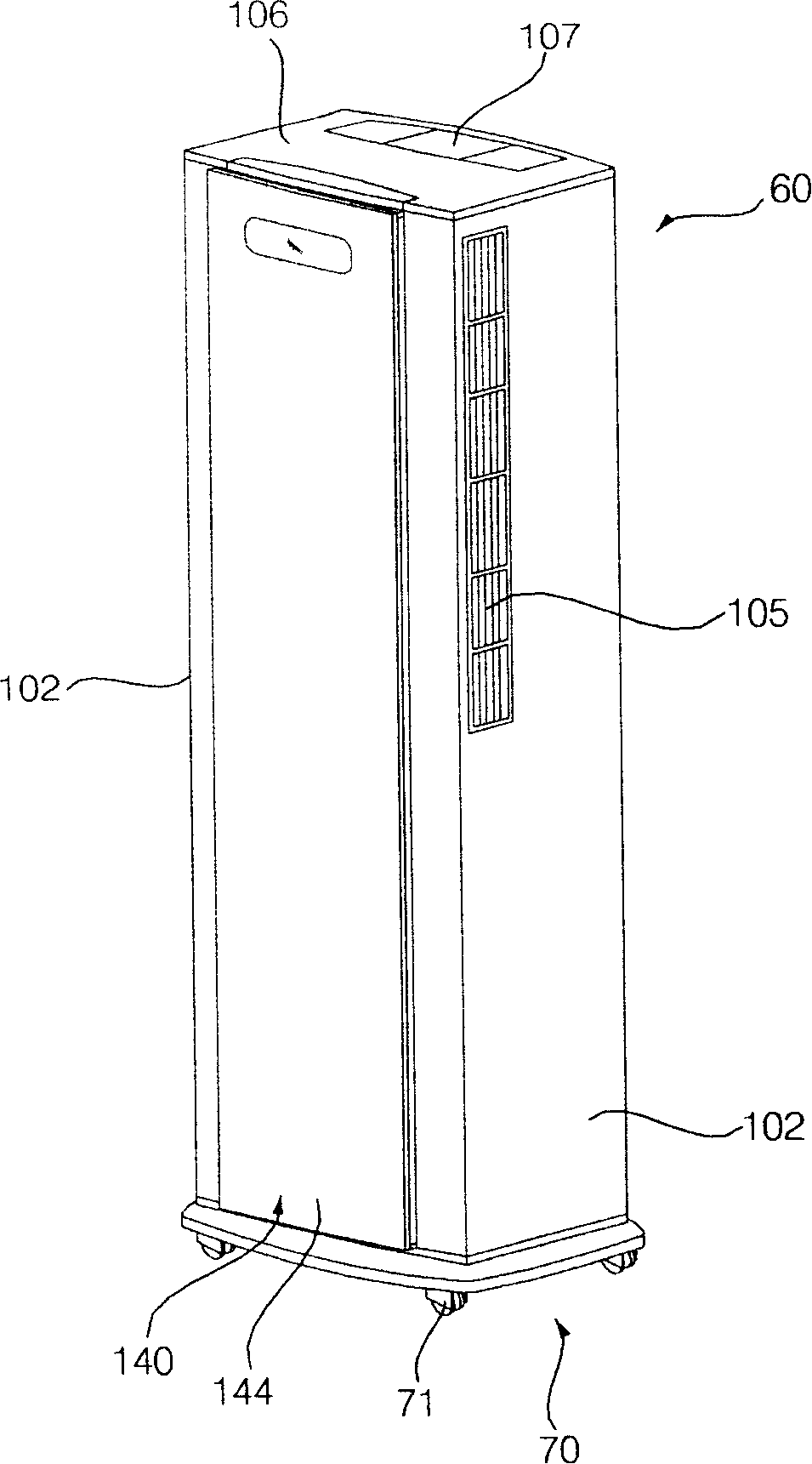
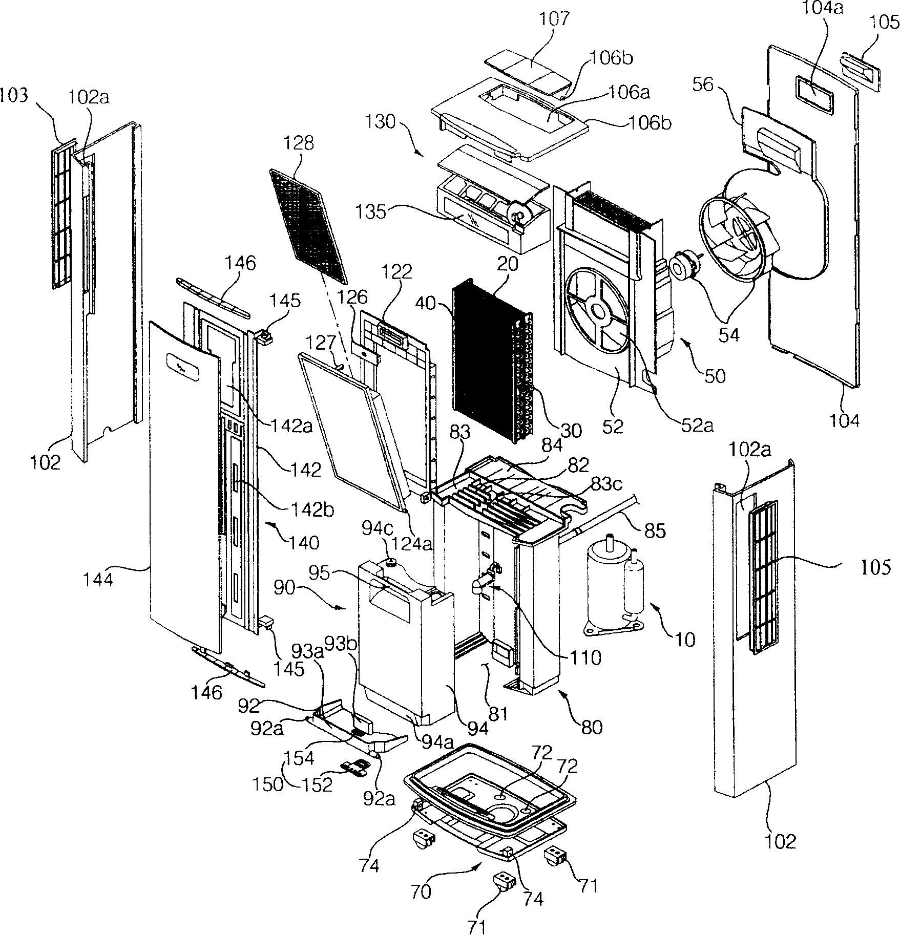
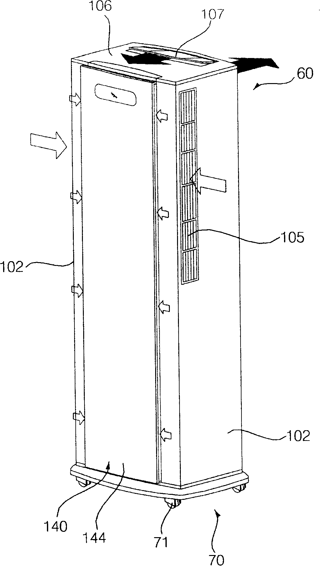
[0051] figure 1 is a perspective view of the dehumidifier of the present invention, figure 2 It is an exploded perspective view of the dehumidifier of the present invention, image 3 It is a schematic diagram of air flow when the dehumidifier of the present invention works, Figure 4 It is a schematic diagram of the separation process of the water receiving bucket of the present invention.

[0052] Such as figure 1 or figure 2 As shown, the dehumidifier of the present invention includes: a compressor 10 for compressing a refrigerant; a condenser 20 for condensing the refrigerant compressed by the compressor 10; an expansion valve 30 for expanding the condensed refrigerant into mist liquid; The evaporator 40 for evaporating the refrigerant expanded by the expansion valve 30; the blower fan assembly 50 provided to make indoor air flow through the evaporat...


PUM


Abstract

The invention provides a dehumidifier, which comprises a baffle arranged on a base, a water draining tray arranged at the upper part of the baffle and used for collecting the condensed water and provided with a condensed water draining water collecting mouth, a water holding barrel groupware arranged at the upper part of the base and used for storing/draining the condensed water falling through the water collecting mouth, a water draining hose connected with the water collecting mouth for draining the condensed water, and a hose fixing device arranged at the inner side of the baffle and used for fixing the water draining hose. The invention has the effects that the dehumidifier can prevent the water draining hose from shaking caused by the flowing of the condensed water when the condensed water is drained through the water draining hose and the water draining hose can be stably fixed in the interior of the dehumidifier when the water draining hose is not used. Because of the water holding barrel groupware of the dehumidifier, the water collecting mouth can be selectively connected with the water holding barrel groupware or the water draining hose so as to drain the condensed water. A guiding part of the water holding barrel of the dehumidifier can rotate forwards along with the water holding barrel so as to complete the separation of the water holding barrel by the simplest action.

Description

technical field [0001] The present invention relates to a dehumidifier, and more particularly to a dehumidifier in which a drain hose for discharging condensed water falling from a drain pan to the outside can be fixed. Background technique [0002] Generally speaking, the dehumidifier sucks the humid air in the room into the inside of the casing, and makes it flow through a heat exchanger composed of an evaporator and a condenser flowing with a refrigerant, thereby reducing the humidity, and then dehumidifies the dehumidified air. A device that re-discharges air into the room, thereby reducing the humidity in the room. [0003] A dehumidifier in the prior art includes: a casing that constitutes an overall appearance and is formed with an air suction port and an air discharge port; it is arranged inside the casing, and is equipped with an evaporator and a condenser to dehumidify the sucked air. A heat exchanger composed of a heat exchanger; a compressor that is connected to...

Claims


Application Information

Patent Timeline
Patent Type & Authority Applications(China)
IPC IPC(8): F24F1/02F24F13/22
Inventor 金正勋
Owner LG ELECTRONICS (TIANJIN) APPLIANCES CO LTD
Why Eureka
Try Eureka