Check patentability & draft patents in minutes with Patsnap Eureka AI!

Thin film capable of enhancing brightness

A brightness and thin film technology, applied in optics, instruments, nonlinear optics, etc., can solve the problems of increasing the thickness of the backlight module and the manufacturing cost of components in the backlight module, and achieve the effect of reducing the manufacturing cost and quantity.

Inactive Publication Date: 2008-05-14
SPEED TECH
View PDF0 Cites 0 Cited by
  • Summary
  • Abstract
  • Description
  • Claims
  • Application Information

AI Technical Summary

Problems solved by technology

However, this will increase the thickness of the entire backlight module, the number of components in the backlight module and its production cost

Method used


Image

  • Thin film capable of enhancing brightness
  • Thin film capable of enhancing brightness
  • Thin film capable of enhancing brightness

Examples


Embodiment Construction

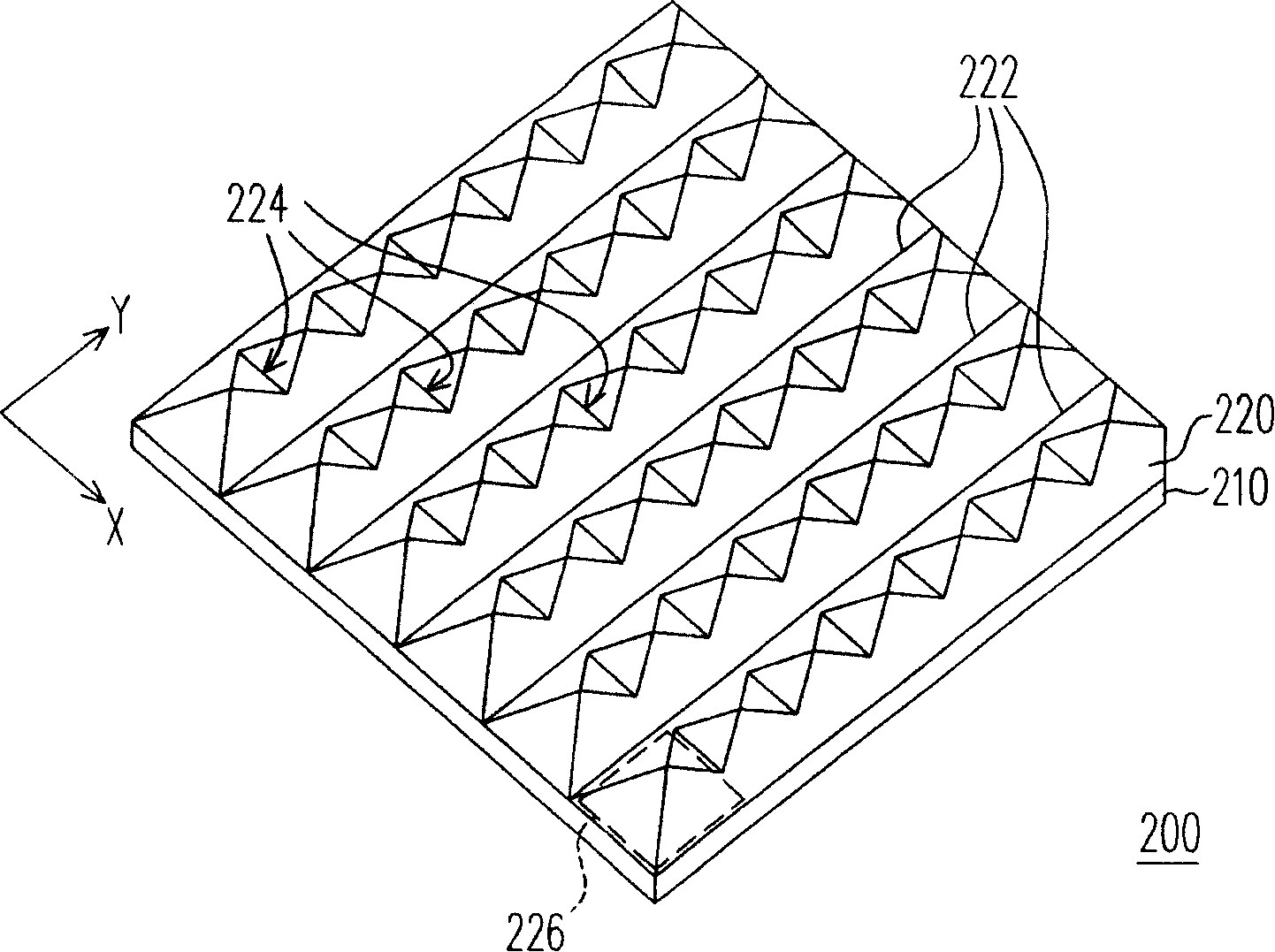
[0026] Figure 3A It is a three-dimensional schematic diagram of a film that can improve brightness according to an embodiment of the present invention; Figure 3B for along Figure 3A A schematic side view of a film that can improve brightness drawn in the X direction in ; Figure 3C for along Figure 3A Schematic side view of the brightness-enhancing film drawn in the Y direction in . Please also refer to Figure 3A , 3B And 3C, the brightness-enhancing film 200 mainly includes a substrate 210 and a brightness-enhancing structure 220 disposed on the substrate 210 . The surface of the brightness-enhancing structure 220 has a plurality of first grooves 222 arranged along the first direction (ie, the Y axis) and a plurality of second grooves 224 arranged along the second direction (ie, the X axis). The arrangement of the first grooves 222 and the second grooves 224 is perpendicular to each other, so as to define a plurality of bevel mirror units 226 arranged in an array. ...


PUM

PropertyMeasurementUnit
Diameteraaaaaaaaaa

Abstract

The invention relates to a film which can improve the brightness and comprises a base material and a structure which is arranged on the base material and can improve the brightness. The surface of the structure which can improves the brightness is provided with a plurality of first grooves which are arrayed along a first direction and a plurality of second grooves which are arrayed along a second direction; the first direction is crossed with the second direction, and the first grooves as well as the second grooves are used for defining a plurality of pyramidal flat inclined mirror units; wherein, partial first grooves have the depth of a second groove while the partial second grooves have the depth of a first groove and the depths of the first grooves are not equal to the depth of the second grooves.

Description

technical field [0001] The present invention relates to a luminance improvement film, and in particular to a luminance improvement film used in a backlight module. Background technique [0002] The rapid progress of the multimedia society is mostly due to the rapid progress of semiconductor components or man-machine display devices. As far as the display is concerned, the cathode ray tube (Cathode Ray Tube, CRT) has been monopolizing the display market in recent years because of its excellent display quality and economy. However, for the environment where individuals operate most terminals / display devices on the table, either from the perspective of environmental protection, or from the trend of energy saving, there are still many problems in the space utilization and energy consumption of cathode ray tubes, and There is no effective solution to the demands of lightness, thinness, shortness, smallness and low power consumption. Therefore, liquid crystal displays (Liquid Cr...

Claims


Application Information

Patent Timeline
IPC IPC(8): G02B5/00G02B1/04G02F1/1335
Inventor 江如鑫
Owner SPEED TECH
Features
  • R&D
  • Intellectual Property
  • Life Sciences
  • Materials
  • Tech Scout
  • Unparalleled Data Quality
  • Higher Quality Content
  • 60% Fewer Hallucinations
Learn More