Glue dropping device

A dispensing device and dispensing technology, which is applied in dispensing devices, special dispensing devices, installation, etc., can solve the problems of dispensing needle 13a damage, production pause, lens barrel rotating away from the axis, etc., and avoid dispensing needle damage Effect

Inactive Publication Date: 2008-05-14
HONG FU JIN PRECISION IND (SHENZHEN) CO LTD +1
View PDF0 Cites 7 Cited by
  • Summary
  • Abstract
  • Description
  • Claims
  • Application Information

AI Technical Summary

Problems solved by technology

However, during the dispensing process, errors such as positioning deviation of the dispensing needle and rotation of the lens barrel away from the axis often occur, especially when the lens barrel is high and the spacer ring is small
When these errors occur, since the dispensing syringe 12a is fixedly mounted on the holding device 15a, the dispensing needle 13a cannot be retracted, so that the dispensing needle 13a rigidly contacts the lens barrel, spacer ring or other parts to be dispensed. The dispensing needle 13a is damaged or even broken due to collision, which further leads to production stoppage, reduced production efficiency and increased production time

Method used


Image

  • Glue dropping device
  • Glue dropping device
  • Glue dropping device

Examples


no. 1 example

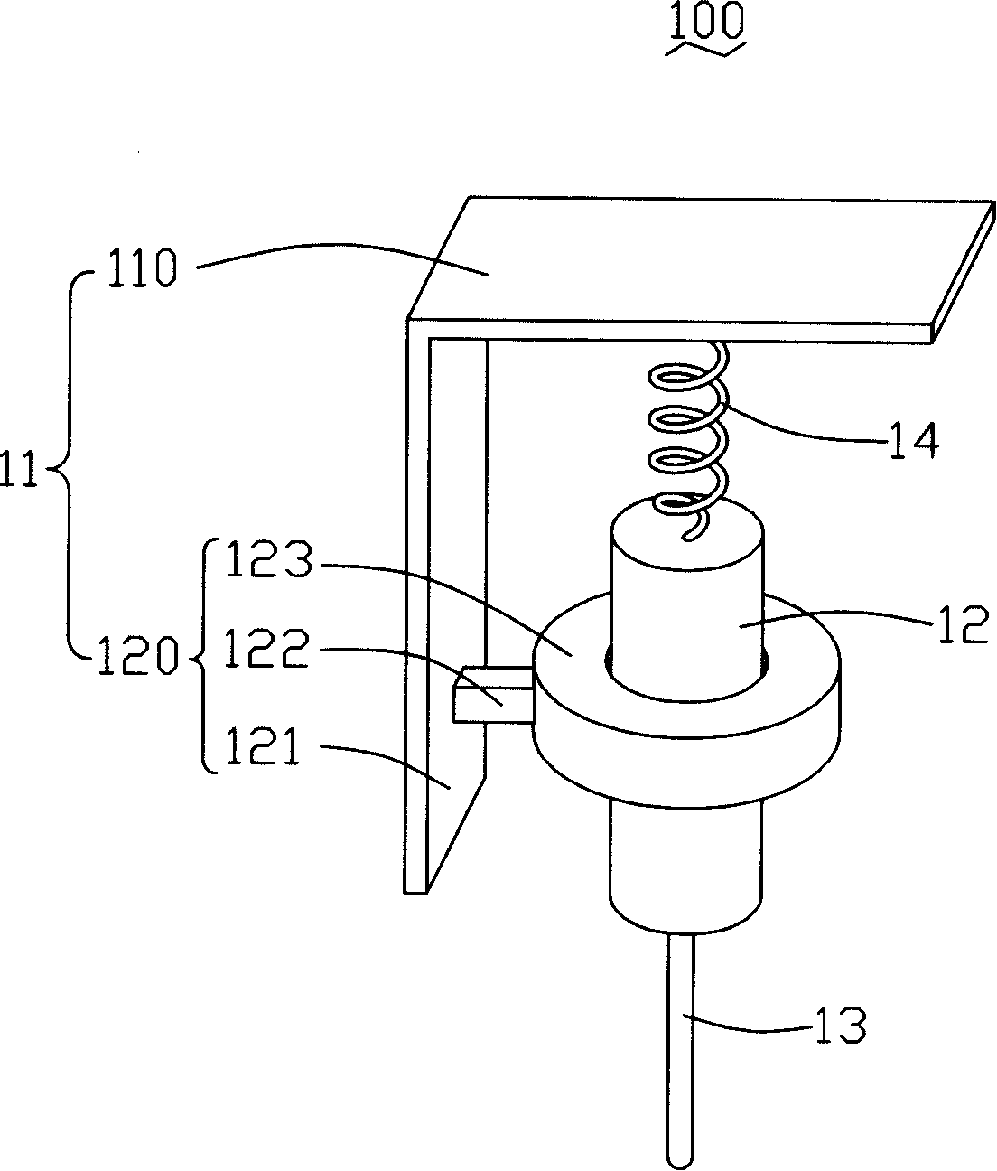
[0012] see figure 1 , the dispensing device 100 of this embodiment includes a holding device 11 , a dispensing syringe 12 , a dispensing needle 13 and an elastic element 14 . The dispensing needle 13 is arranged at the bottom of the dispensing syringe 12 , and the top of the dispensing syringe 12 is connected with the holding device 11 through the elastic element 14 .

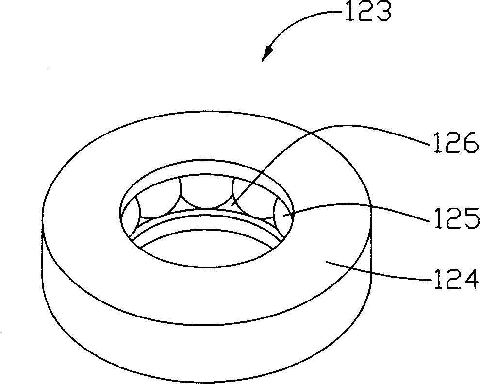
[0013] The holding device 11 of this embodiment includes a first holding portion 110 and a second holding portion 120 . The first holding part 110 is plate-shaped, and is disposed on the top of the second holding part 120 , and the elastic element 14 is connected thereon. The second holding portion 120 includes a holding seat 121 and at least one holding collar 123 . The holding collar 123 is used to sheath the dispensing syringe 12 , which can be directly fixed on the holding seat 121 , or can be set on the holding seat 121 through the holding arm 122 . The second holding portion 120 of this embodiment inc...

no. 2 example

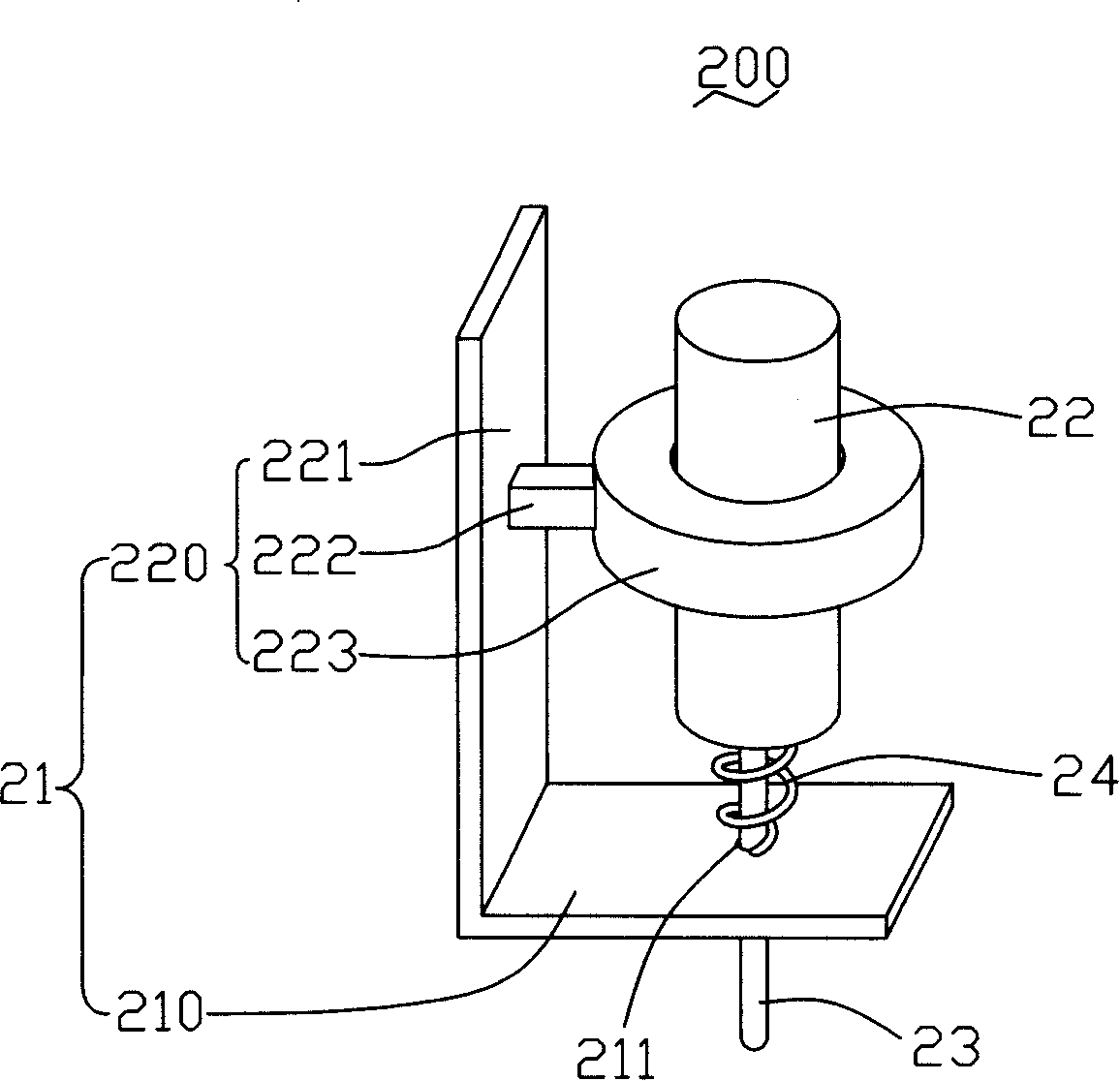
[0019] see image 3 The dispensing device 200 of this embodiment includes a holding device 21, a dispensing syringe 22, a dispensing needle 23 and an elastic element 24 arranged at the bottom of the dispensing syringe 22, and the holding device 21 includes a first holding part 210 and a second holding part 210. The holding part 220 , the first holding part 210 is disposed at the bottom of the second holding part 220 , and the bottom end of the dispensing syringe 22 is connected to the first holding part 210 through the elastic element 24 .

[0020] In this embodiment, the first holding portion 210 is plate-shaped, and a hole 211 is provided in the middle for the dispensing needle 23 to pass through. The radius of the hole 211 should be slightly larger than the radius of the dispensing needle 23 . The second holding part 220 is the same as the second holding part 120 of the first embodiment, and also includes a holding seat 221 , a holding arm 222 and a holding ring 223 for co...

no. 3 example

[0024] Of course, both ends of the dispensing syringe can be connected to the holding device through elastic elements. see Figure 4 The dispensing device 300 of the third embodiment of the present invention includes a holding device 31 , a dispensing syringe 32 , a dispensing needle 33 disposed at the bottom of the dispensing syringe 32 , a first elastic element 34 and a second elastic element 35 . The first elastic element 34 connects the holding device 31 and the top end of the dispensing syringe 32 , and the second elastic element 35 connects the holding device 31 and the bottom end of the dispensing syringe 32 .

[0025] The holding device 31 is in the form of a semi-cylindrical body for accommodating the dispensing syringe 32 . The holding device 31 includes a first holding portion 310 , a second holding portion 320 and a third holding portion 330 . Wherein, both the first holding part 310 and the third holding part 330 can be semicircular plates, which are respectivel...


PUM


Abstract

The invention provides a glue dropping device which comprises a firm holding device, a glue dropping syringe and a glue dropping pinhead which is positioned on one end of the glue dropping syringe. Elastic components are connected between the firm holding device and at least one end of the glue dropping syringe. When the glue dropping pinhead of the glue dropping device occurs rigid collision with the parts waiting for the glue dropping, the glue dropping syringe and the glue dropping pinhead can move and lead the elastic components to occur distortion, thus preventing the glue dropping pinhead from being damaged or broken caused by the rigid collision occurred by the parts waiting for the glue dropping.

Description

technical field [0001] The invention relates to a glue dispensing device, in particular to a glue dispensing device which can be used for lens module assembly. Background technique [0002] During the assembly process of the lens module, in order to fix small parts such as lenses, gaskets, spacers and filters in the lens barrel, one or more dispensing processes are usually carried out after the aforementioned small parts are loaded into the lens barrel to fix the small parts. Parts are fixed in the lens barrel. The glue dispensing process is carried out by the glue dispensing device. see Figure 5 , the traditional dispensing device 10a includes a base 11a, a dispensing syringe 12a and a dispensing needle 13a disposed at one end of the dispensing syringe 12a. The dispensing syringe barrel 12a is fixedly installed on the holding device 15a of the base 11a through bolts 14a. When dispensing glue, the dispensing needle 13a is positioned at the position to be dispensed and th...

Claims


Application Information

Patent Timeline
Patent Type & Authority Applications(China)
IPC IPC(8): G02B7/02B67D7/84
CPCB05C5/02
Inventor 余泰成
Owner HONG FU JIN PRECISION IND (SHENZHEN) CO LTD
Why Eureka
Try Eureka