
Timepiece including a correction mechanism for a device displaying a time quantity

A display device and a time-related technology, applied in the field of clocks and watches, can solve the problem of no disclosure of actuating control cams and the like

Active Publication Date: 2008-05-14
CO DES MONTRES LONGINES FRANCILLON SA
View PDF5 Cites 18 Cited by
  • Summary
  • Abstract
  • Description
  • Claims
  • Application Information

AI Technical Summary

Problems solved by technology

However, it does not disclose actuating the control cam via a return cam cooperating with a cam profile provided on the inner periphery of the ring cam

Method used


Image

  • Timepiece including a correction mechanism for a device displaying a time quantity
  • Timepiece including a correction mechanism for a device displaying a time quantity
  • Timepiece including a correction mechanism for a device displaying a time quantity

Examples


Embodiment Construction

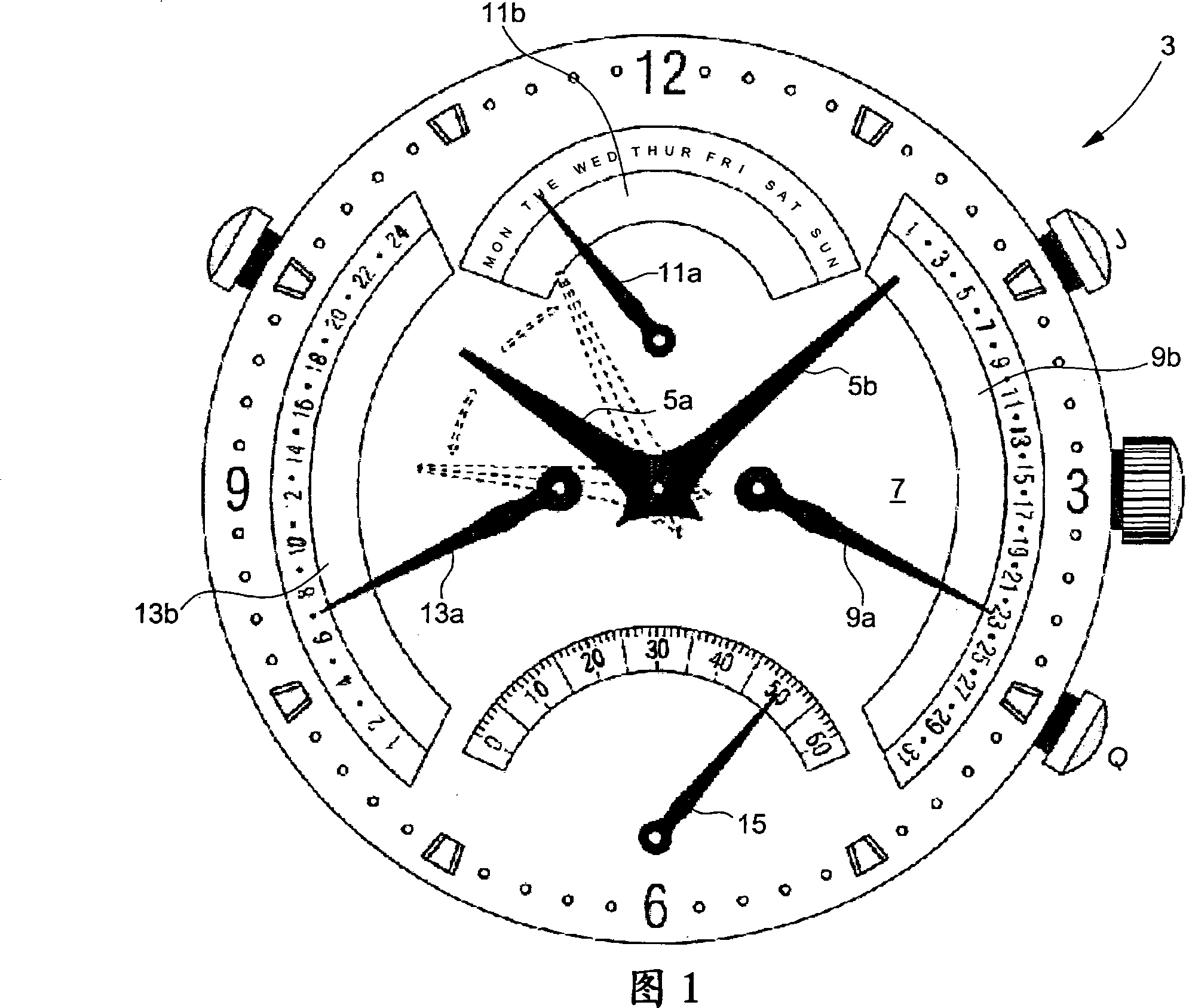
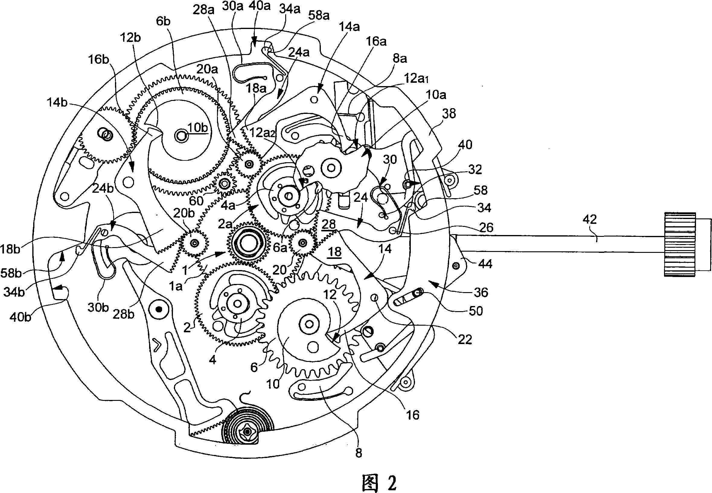
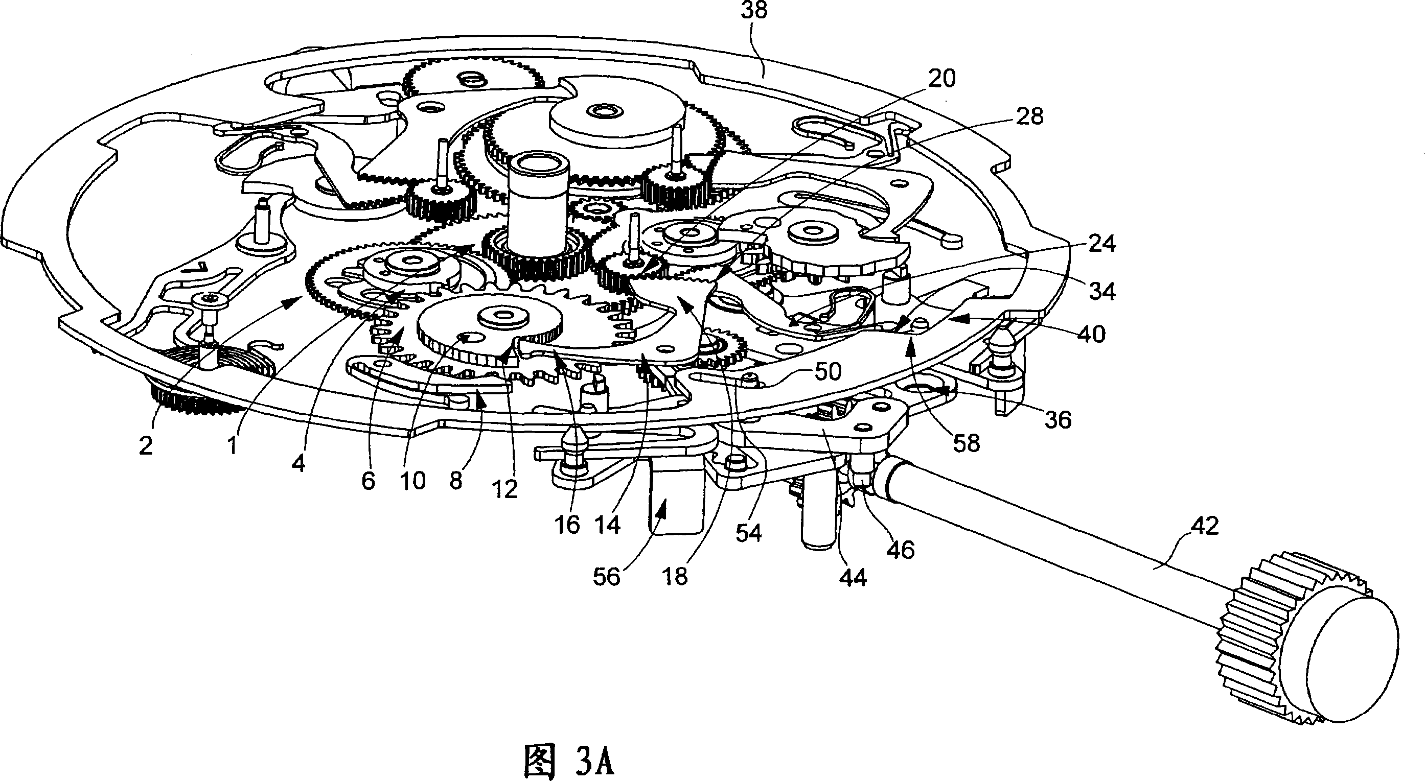
[0019] The present invention stems from the general inventive idea of ​​providing a timepiece comprising an adjustment mechanism for a display device of a time-related quantity, such as a date device, capable of adjusting the device in two directions, ie forwards and backwards. In order to achieve this object, the invention suggests that, during the backward adjustment phase, the control lever of the display device must be moved out of the path of the cam. There is therefore provided a disconnect or disconnect mechanism, which is actuated by the control stem, via another lever, called the return lever, to move the arm of the control lever away from the cam against which it normally rests.

[0020] The present invention will be described below in conjunction with the date display device. However, it will be clear from reading this description that the invention is not limited to date display devices, but is equally applicable to day calendar display devices, 24-hour display dev...


PUM


Abstract

The invention relates to a timepiece including a two-directional correction mechanism for a device displaying a time related quantity, the display device is actuated by a control lever ( 14 ) itself controlled by a cam ( 10 ), on which the control lever ( 14 ) abuts, the timepiece being characterized in that it includes a correction device ( 36 ) activated by a control stem ( 42 ) which, in the display device correction phase, via a return lever ( 24 ), moves the control lever ( 14 ) out of the path of the cam ( 10 ) on which said control lever ( 14 ) normally abuts in the normal operating phase of the timepiece ( 3 ).

Description

technical field [0001] The invention relates to a timepiece with a mechanism comprising display means for adjusting / correcting time-related quantities. More specifically, the invention relates to a timepiece of the type comprising a bidirectional adjustment mechanism for means for displaying time-related quantities, such as a calendar mechanism. Background technique [0002] Devices that display time-related quantities, such as calendar mechanisms, are mostly based on a system with a control arm that travels along the profile of a cam and actuates the date indicator part each day. Typically, at one point in its profile, the cam has a steep face or step that marks the transition from the last day of a given month to the first day of the next month. The presence of this steep face at a point on the cam profile causes problems when one wishes to adjust, for example, the date indication in the counterclockwise direction. In fact, when it is desired to adjust the date indicatin...

Claims


Application Information

Patent Timeline
IPC IPC(8): G04B19/24G04B19/25G04B27/00
CPCG04B19/25G04B19/082G04B27/004G04B19/02
Inventor A·布龙O·马勒A·卡贝萨斯·朱林
Owner CO DES MONTRES LONGINES FRANCILLON SA
Learn More