Piston limiting structure, compressor and heat exchange equipment

A technology of limiting structure and heat exchange equipment, applied in the field of compressors, can solve the problems of introducing natural clearance volume, high processing technology requirements, and introducing clearance volume, etc., and achieves easy processing, firm structure and reduced gear size. Effect

Pending Publication Date: 2019-04-02
GREE ELECTRIC APPLIANCES INC
View PDF0 Cites 4 Cited by
  • Summary
  • Abstract
  • Description
  • Claims
  • Application Information

AI Technical Summary

Problems solved by technology

[0007] In order to solve the technical problem that the circular piston in the prior art will rotate and cause the piston head to interfere with the inner wall of the cylinder liner or even hit the cylinder, and at the same time, the limit structure between the circular piston and the cylinder will introduce a natural clearance volume. The present invention provides A piston limit structure that prevents the piston from rotating and has high matching precision will not introduce clearance volume
[0008] At the same time, in order to solve the technical problem that the circular piston limiting structure in the existing rotary cylinder piston compressor will introduce clearance volume and have high requirements for processing technology, the present invention provides a circular piston that does not introduce clearance volume. piston compressor

Method used


Image

  • Piston limiting structure, compressor and heat exchange equipment
  • Piston limiting structure, compressor and heat exchange equipment
  • Piston limiting structure, compressor and heat exchange equipment

Examples


Embodiment Construction

[0061] The technical solutions of the present invention will be clearly and completely described below in conjunction with the accompanying drawings. Apparently, the described embodiments are some of the embodiments of the present invention, but not all of them. Based on the embodiments of the present invention, all other embodiments obtained by persons of ordinary skill in the art without making creative efforts belong to the protection scope of the present invention. In addition, the technical features involved in different embodiments of the present invention described below may be combined with each other as long as they do not constitute a conflict with each other.

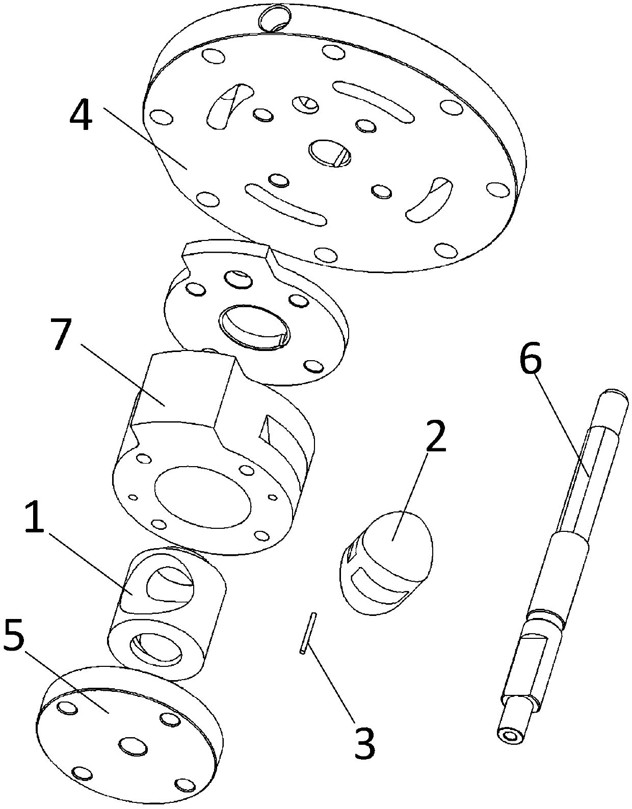
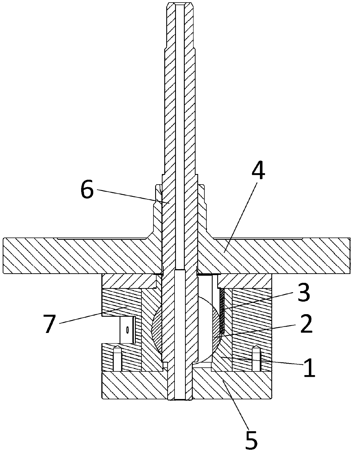
[0062] The rotary cylinder piston compressor in the prior art includes a flange, a cylinder liner, a cylinder, a piston and a rotating shaft. Based on the principle of the cross slider, the piston reciprocates sliding relative to the cylinder during rotation, so that the two ends of the piston are connected wi...


PUM


Abstract

The invention relates to the field of compressors, in particular to a piston limiting structure, a compressor and heat exchange equipment. The piston limiting structure comprises an air cylinder, a piston and a limiting part. The air cylinder is provided with a piston hole, wherein the piston hole is perpendicular to the axis direction of the air cylinder and penetrates through the air cylinder, and the projection of the piston hole in the penetrating direction is circular. The piston is arranged in the piston hole in a matched shape mode and can slide in the piston hole in a reciprocating mode. A limiting surface is formed in the side wall of the piston. The length part, in the axis direction of the piston, of the limiting surface does not penetrate through the two ends of the side wall of the piston. The air cylinder is provided with a limiting hole penetrating from the outer wall of the air cylinder to the piston hole. The limiting part is arranged in the limiting hole in a matchedshape mode and abuts against the limiting surface to limit the piston to rotate around the axis of the piston. According to the piston limiting mechanism, clearance volume is not introduced, so that the piston limiting effect is better.

Description

technical field [0001] The invention relates to the field of compressors, in particular to a piston limiting structure, a compressor and heat exchange equipment. Background technique [0002] Rotary cylinder piston compressor is a compressor based on the principle of cross sliders. The cylinder rotates in the cylinder liner, and the piston is horizontally arranged in the piston hole of the cylinder, and slides reciprocally in the piston hole, so that the end surface of the piston, A compression cavity is formed between the side wall of the piston hole and the inner wall of the cylinder liner. [0003] In order to ensure the degree of fit and applicability between the piston and the piston hole, from a manufacturing point of view, it is obviously optimal to use a circular piston hole and a piston with a cylindrical cross-section, and it is easiest to ensure machining accuracy. However, in this case, since the piston hole is arranged laterally in the cylindrical piston, the t...

Claims


Application Information

Patent Timeline
Patent Type & Authority Applications(China)
IPC IPC(8): F04C18/344F04C29/00
CPCF04C18/344F04C29/00F04C2240/30F04C2240/20F01C21/0836F01C21/08F04C29/04F04C2270/17
Inventor 胡余生魏会军徐嘉杜忠诚杨森李直任丽萍梁社兵张荣婷史正良丁宁郭霜廖李平
Owner GREE ELECTRIC APPLIANCES INC
Why Eureka
Try Eureka