Method and arrangement for determination of the residual capacity of breathable air for an oxygen-generating breathing apparatus operated in circuit

A technology of circuit control and residual gas volume, which is applied in the direction of respiratory protection devices, life-saving equipment, fire rescue, etc., and can solve the problems that maintenance cannot be carried out immediately

Inactive Publication Date: 2008-05-14
MSA EURO
View PDF1 Cites 9 Cited by
  • Summary
  • Abstract
  • Description
  • Claims
  • Application Information

AI Technical Summary

Problems solved by technology

In addition, this maintenance cannot be carried out immediately, it can only be carried out when the temperature of the blower is below 30°C

Method used


Image

  • Method and arrangement for determination of the residual capacity of breathable air for an oxygen-generating breathing apparatus operated in circuit

Examples


Embodiment Construction

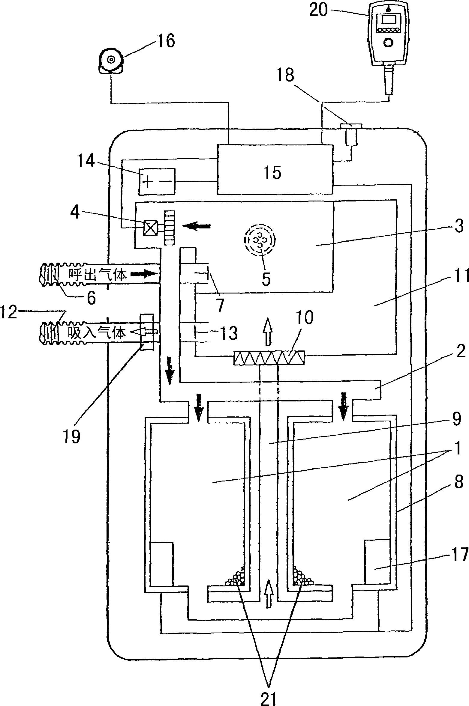
[0011] The respirator comprises two chemical tanks 1 arranged in parallel circuit, said chemical tanks being connected via a gas distributor 2 to an exhalation bag 3 equipped with a blower 4 . An excess valve 5 is integrally mounted on the wall of the exhalation bag 3 . An exhalation tube 6 with an exhalation valve 7 is connected to the exhalation bag 3 . Chemical tank 1 has a cooling jacket 8 and uses potassium superoxide (KO 2 ) particles 21 filled. A connecting pipe 9 connects the outlets of the two chemical tanks 1 with a suction bag 11 through a particle filter 10 . A suction tube 12 with a suction valve 13 is inserted into the suction bag 11 . The exhalation valve 7 and inhalation valve 13 are connected to a valve controller (not shown).

[0012] The exhaled gas rich in carbon dioxide flows into the exhalation bag 3 through the open exhalation valve 7 (while the inhalation valve 13 is closed) and is pressurized by the blower 4, and passes through the gas distributor ...


PUM


Abstract

Determining the residual volume of breathable air remaining in a circuit-controlled oxygen respirator at any point in time by measuring the number of breathing cycles and measuring the pressure and temperature of the breathing air during successive cycles with pressure and temperature sensors. The air utilization rate breathed at that time is calculated for each time period and subtracted from the total air volume. Displays the residual volume of breathable air at a particular reading point on a display.

Description

technical field [0001] The invention relates to a method for determining the residual volume of breathable air in an electronically controlled oxygen respirator having at least one chemical tank, and a device for implementing the method. The chemical tank is connected to an exhalation bag with an integrated blower and an inhalation bag with an inhalation tube. Background technique [0002] For example, a breathing apparatus is known from DE 44 11 560 which is controlled by an electric circuit and has a consumption display for displaying the volume of breathable air still remaining during use. An air blower is installed on an exhalation bag, and the exhalation valve is behind the exhalation bag. With the aid of a blower, the exhaled air is forced through two chemical tanks arranged in parallel. Since the chemical tank is placed downstream, the breathing resistance to be overcome by the user when exhaling can be significantly reduced by means of the blower. The chemical con...

Claims


Application Information

Patent Timeline
Patent Type & Authority Applications(China)
IPC IPC(8): A62B7/08
CPCA62B7/08
Inventor 弗兰克·克鲁格卡尔-汉兹·费尔德内
Owner MSA EURO
Why Eureka
Try Eureka