Magnetic write head employing multiple magnetomotive force sources

A technology of magnetomotive force and pole magnetism, applied in the field of magnetic write head, which can solve the problems of write field loss and so on

Inactive Publication Date: 2008-05-21
HITACHI GLOBAL STORAGE TECH NETHERLANDS BV
View PDF0 Cites 5 Cited by
  • Summary
  • Abstract
  • Description
  • Claims
  • Application Information

AI Technical Summary

Problems solved by technology

Unfortunately, this means that a certain amount of write field is lost into the trailing shield

Method used


Image

  • Magnetic write head employing multiple magnetomotive force sources
  • Magnetic write head employing multiple magnetomotive force sources
  • Magnetic write head employing multiple magnetomotive force sources

Examples


Embodiment Construction

[0025] The following description is of what is presently contemplated as the preferred mode of carrying out the invention. This description is made for the purpose of illustrating the general principles of the invention and is not intended to limit the inventive concepts presented herein.

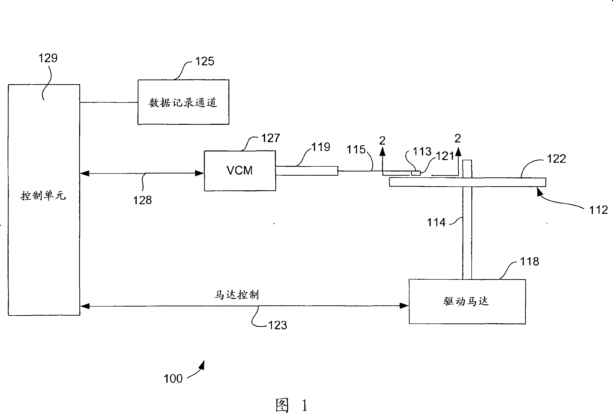
[0026] Referring now to FIG. 1, a disc drive 100 embodying the present invention is shown. As shown in FIG. 1 , at least one rotatable magnetic disk 112 is supported on a spindle 114 and rotated by a disk drive motor 118 . The magnetic recording on each disk is in the form of an annular pattern of concentric data tracks (not shown) on disk 112 .

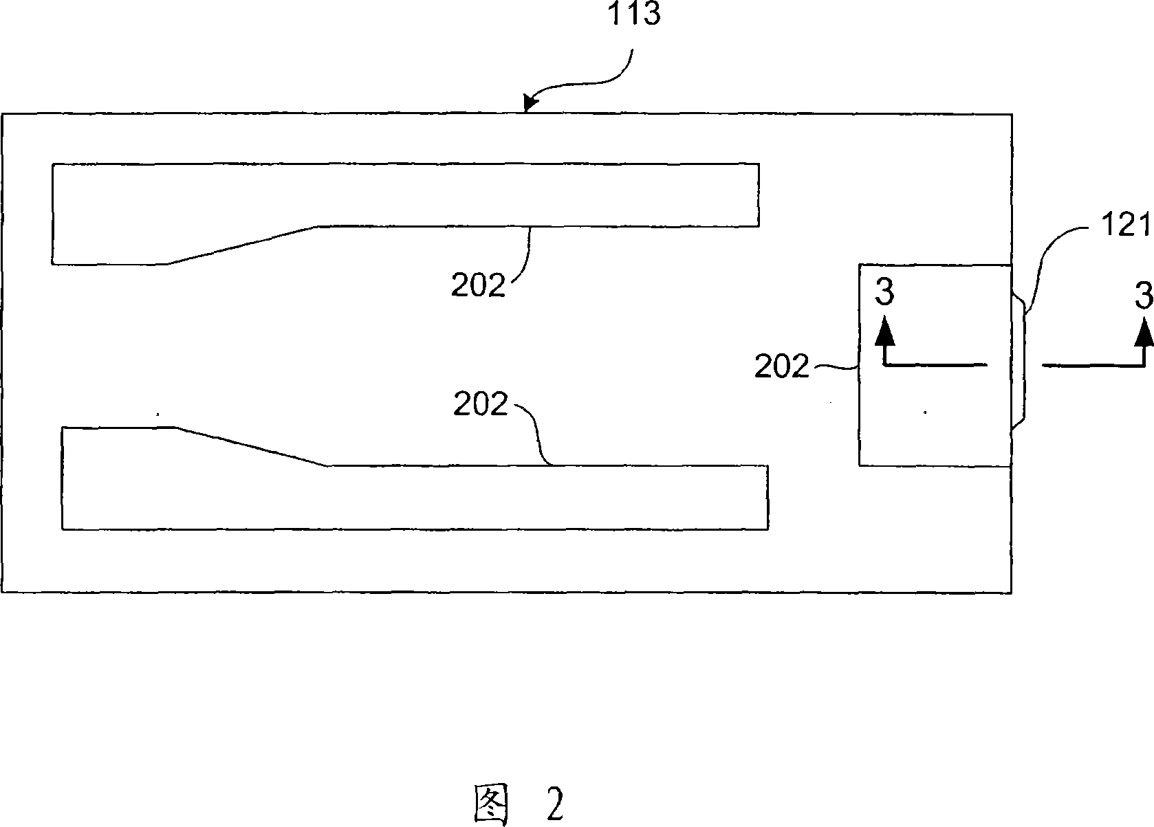
[0027] At least one slider 113 is located adjacent to the magnetic disk 112 , and each slider 113 supports one or more magnetic head assemblies 121 . As the disk rotates, the slider 113 moves radially in and out over the disk surface 122 so that the magnetic head assembly 121 can access different tracks of the disk on which desired data is writt...


PUM


Abstract

A write head for perpendicular magnetic recording having a write pole and first and second return poles. The write head can include a first magnetomotive force source for delivering a magnetomotive force to the first return pole and the write pole and a second magnetomotive force source for delivering magnetomotive force to the second return pole and the write pole. The first and second magnetomotive force sources can be operated independently of one another so that different relative amounts of magnetomotive force can be applied to the first and second return poles. A trailing magnetic shield can be connected with one of the return poles, such as the second return poles, and the variation in magnetomotive force can be used to increase the amount of flux flowing through the trailing shield when increased field gradient is desired (such as when writing a transition), and to decrease the amount of flux through the trailing shield when decreased field gradient and increased write field are desired (such as when writing a long magnetic section on a magnetic medium).

Description

technical field [0001] The present invention relates to magnetic data recording, and in particular to a magnetic write head having a dynamically variable write field generated by multiple magnetomotive force (MMF) sources. Background technique [0002] At the heart of a computer's long-term storage is a component called a disk drive. A disk drive includes a spinning disk, write and read heads suspended by a cantilever adjacent the surface of the spinning disk, and an actuator that rotates the suspension to place the read and write heads on selected tracks on the spinning disk . The read and write heads are located directly on the slider with an air bearing surface (ABS). The cantilever biases the slider toward the surface of the disk, and as the disk rotates, the air adjacent to the disk moves with the surface of the disk. The slider flies above the disk surface on this pad of moving air. The write and read heads are employed to write and read magnetic transitions to and...

Claims


Application Information

Patent Timeline
Patent Type & Authority Applications(China)
IPC IPC(8): G11B5/127G11B5/187G11B5/31G11B5/39
CPCG11B5/1278G11B5/17G11B5/3143G11B5/3123
Inventor 拜伦·H·伦格斯菲尔德第三伊恩·R·麦克法迪恩詹姆斯·L·尼克斯詹姆斯·T·奥尔森彼得勒斯·A·范德海登布鲁斯·威尔逊
Owner HITACHI GLOBAL STORAGE TECH NETHERLANDS BV
Why Eureka
Try Eureka