Disc molding mold, mirror-surface disc, and method for producing mold for disc molding

A metal mold and manufacturing method technology, which is applied to household appliances, other household appliances, applications, etc., can solve the problems of lower flatness and lower accuracy of disc substrates, and achieves reduced contact area, reduced friction coefficient, and prevented wear effect

Inactive Publication Date: 2008-05-21
SUMITOMO HEAVY IND LTD +1
View PDF0 Cites 2 Cited by
  • Summary
  • Abstract
  • Description
  • Claims
  • Application Information

AI Technical Summary

Problems solved by technology

[0007] However, if the flatness of the mounting surface of the mirror disc stamper on which the stamper is mounted decreases, the accuracy of the disc substrate will decrease.

Method used


Image

  • Disc molding mold, mirror-surface disc, and method for producing mold for disc molding

Examples


Embodiment Construction

[0025] Hereinafter, embodiments of the present invention will be described in detail with reference to the drawings. In this case, a disk-forming mold as a mold device disposed on an injection molding machine as a molding machine will be described.

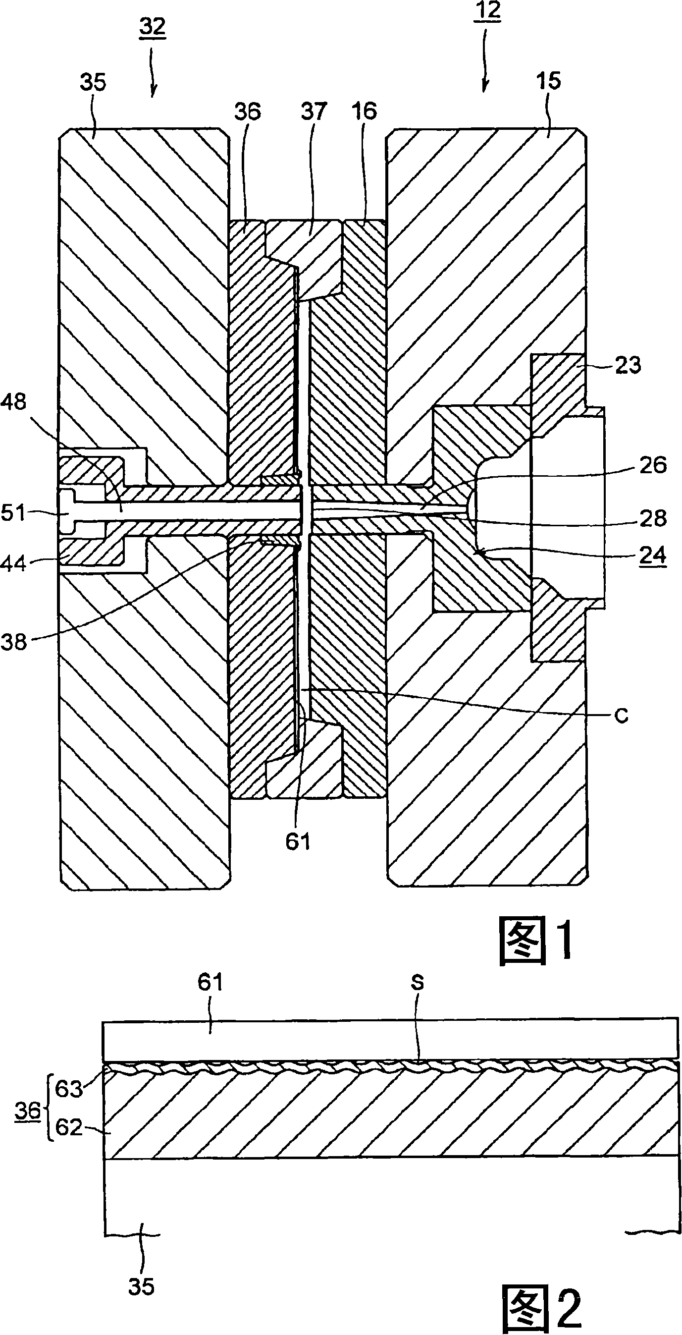
[0026] Fig. 1 is a cross-sectional view of a metal mold for forming a disk in an embodiment of the present invention.

[0027] In the drawings, 12 is a fixed-side metal mold assembly as a first metal mold installed on an unshown fixed platen through an unshown mounting plate. This metal mold assembly 12 includes: The base plate 15 of the support plate; the first mirror plate 16 is installed on the base plate 15; the positioning ring 23 is arranged on the side of the fixed platen in the above-mentioned base plate 15, and the base plate 15 is positioned relative to the fixed platen; and pouring The track sleeve 24 is arranged adjacent to the positioning ring 23 . At the front end of the sprue bushing 24, a mold 28 is formed facing...


PUM

PropertyMeasurementUnit
surface roughnessaaaaaaaaaa
thicknessaaaaaaaaaa

Abstract

A mold which can have improved durability to reduce the mold cost. The mold comprises a first mold and a second mold which faces the first mold and has been disposed so as to be freely movable forward / backward. One of the first and second molds comprises a base whose surface has undergone a roughening treatment and a coating layer formed by subjecting the surface of the base to a coating treatment. A stamper attachment side is formed on the surface of the coating layer. Since the coating layer is formed by subjecting to a coating treatment the base surface which has undergone a surface-roughening treatment, the base / coating layer contact area can be increased. The adhesion between the base and the coating layer can hence be increased. Consequently, the coating layer is less apt to peel off and the mold can have improved durability. A reduction in mold cost can hence be attained.

Description

technical field [0001] The present invention relates to a metal mold for disc molding, a mirror disc and a method for manufacturing the metal mold for disc molding. Background technique [0002] Conventionally, in a molding machine such as an injection molding machine for molding disc substrates, the resin melted in the heating cylinder is filled into the cavity space in the metal mold for disc molding, and the cavity space is filled with resin. Cool and solidify to obtain a disc substrate. [0003] Therefore, the above-mentioned injection molding machine is equipped with: a metal mold for forming a disk, including a fixed-side mold assembly as a first metal mold and a movable-side mold assembly as a second metal mold; and an injection device for filling the above-mentioned resin in a cavity space; and a mold clamping device for joining and separating the metal mold assembly on the movable side from the metal mold assembly on the fixed side. Furthermore, the metal mold ass...

Claims


Application Information

Patent Timeline
Patent Type & Authority Applications(China)
IPC IPC(8): B29C45/37B29C33/38B29L17/00
CPCB29C2045/2634B29C45/263Y10T428/216B29C33/38B29C45/37
Inventor 渋谷裕二稻田雄一
Owner SUMITOMO HEAVY IND LTD
Why Eureka
Try Eureka