Stirring mixer

A technology of mixing and mixing barrels, which is applied in the directions of mixers, mixers, and mixing methods with rotating mixing devices to achieve ideal mixing and mixing effects.

Active Publication Date: 2010-08-25
黎泽荣
View PDF0 Cites 5 Cited by
  • Summary
  • Abstract
  • Description
  • Claims
  • Application Information

AI Technical Summary

Problems solved by technology

This kind of agitator, because the materials to be stirred generally have strong viscosity (such as syrup), when it is necessary to clean and maintain the agitator, it is often difficult to disassemble the agitator due to the bonding effect of the residual material in the agitator. to open

Method used


Image

  • Stirring mixer
  • Stirring mixer
  • Stirring mixer

Examples


Embodiment 1

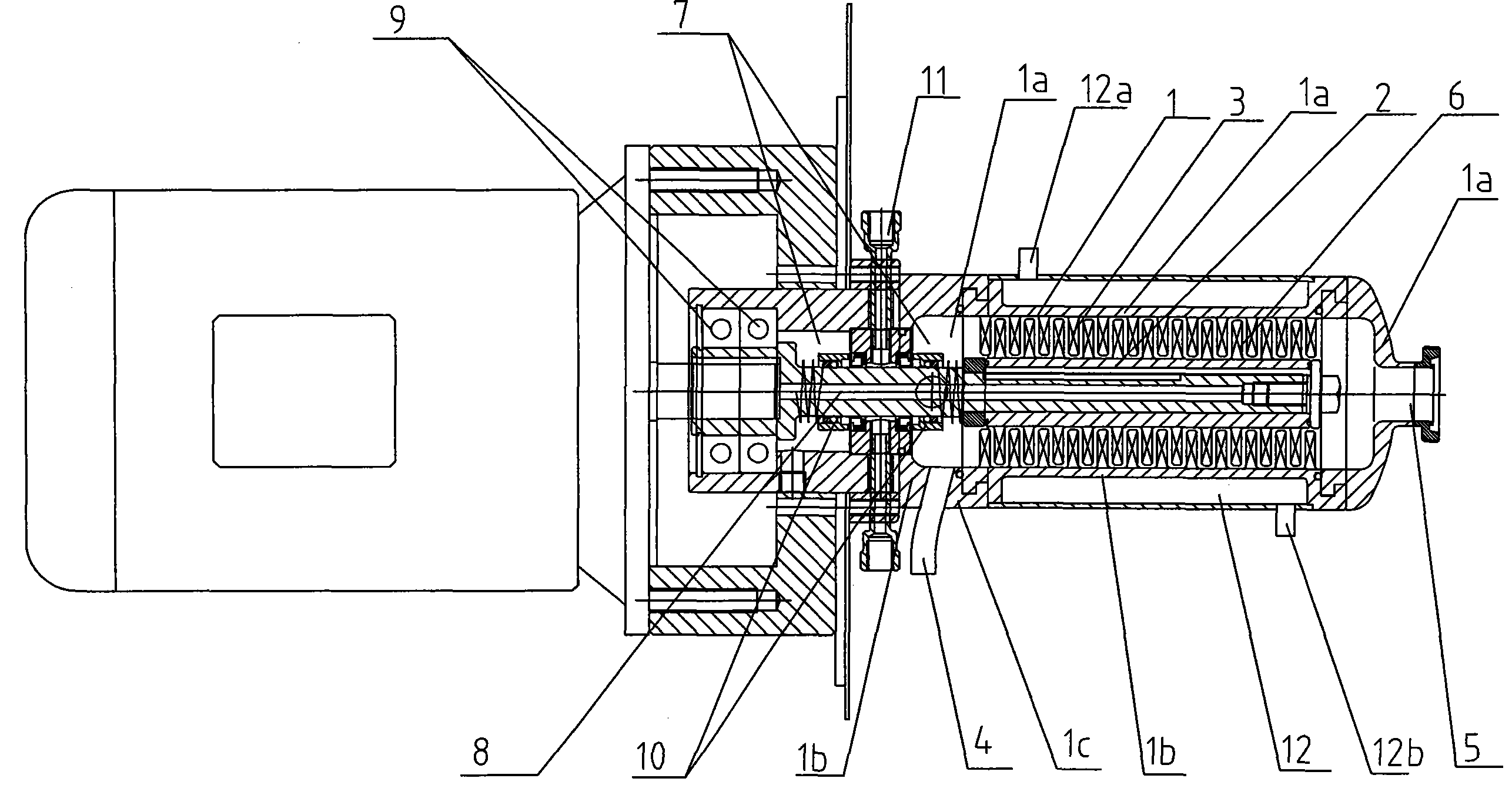
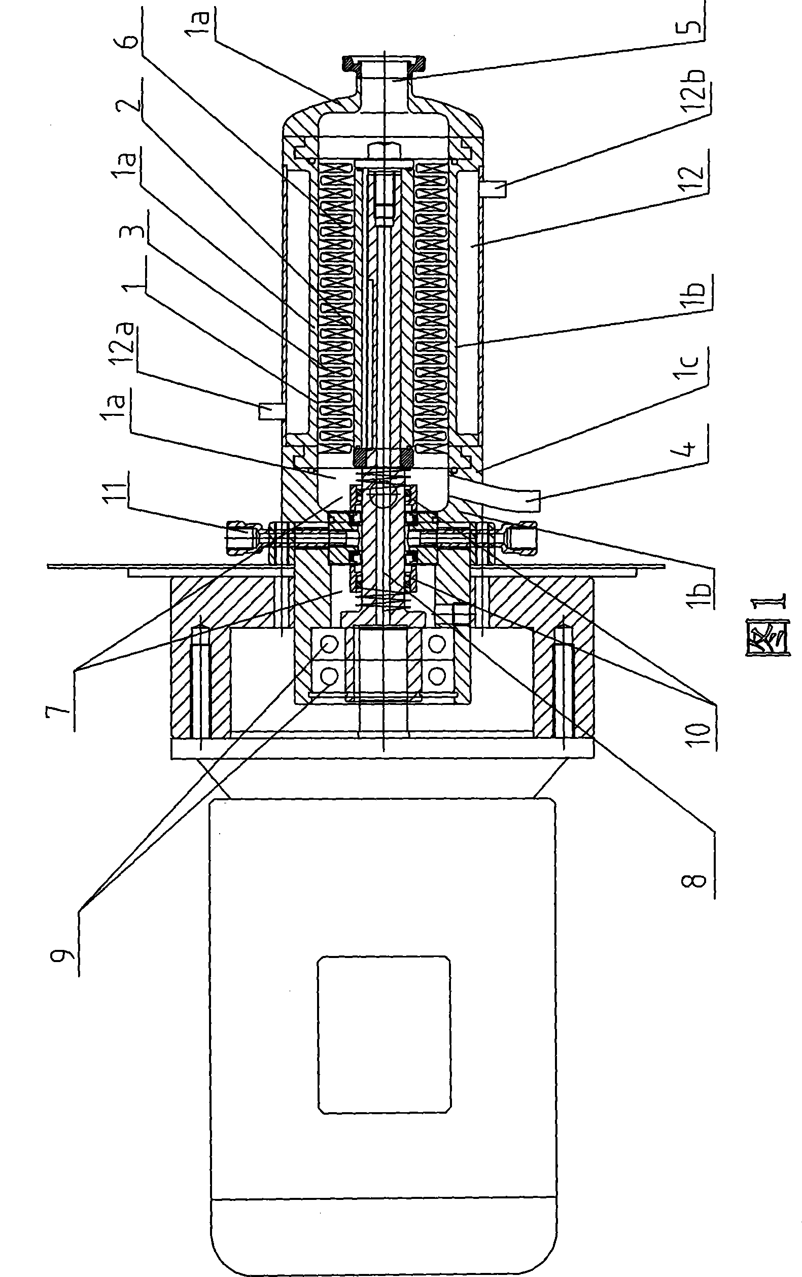
[0018] Embodiment 1: As shown in Figure 1, the present invention comprises shell 1 with material inlet and outlet 4,5, stirring rotating shaft 2, and shell is made of staving 1a, the end cap 1b that is arranged on staving 1a end, in staving 1a The inner wall is evenly arranged with rows of teeth 3 arranged vertically and horizontally. The width of the teeth of each row of teeth 3 is the same. A row of teeth 6 is also provided at the place where the stirring shaft 2 is staggered from the row of teeth 3 on the inner wall of the barrel body 1a. , the inner wall of the barrel body 1a and the row of teeth 3 on the inner wall of the barrel body 1a are integrally manufactured together, and the stirring shaft 2 and the row of teeth 6 arranged on the stirring shaft 2 are also integrally manufactured together. The special feature of the barrel body is that 1a is formed by splicing two or more barrel units 1a1 through bolts and nuts, and a gasket 1a2 is provided at the joint of two adjace...

Embodiment 2

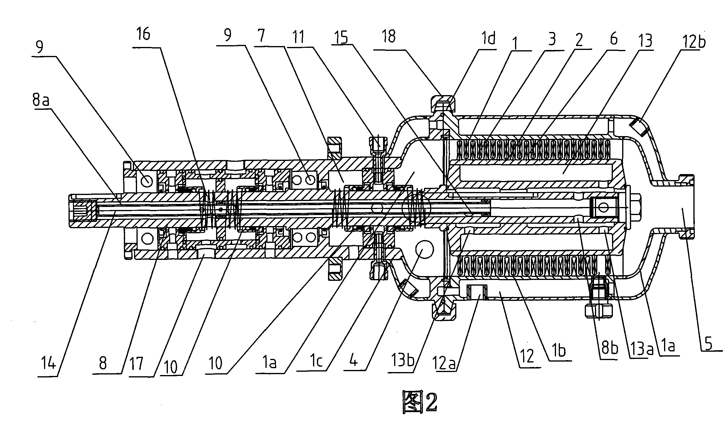
[0020] Embodiment 2: As shown in Figure 2, the present embodiment is based on Embodiment 1 and is provided with the interlayer 13 that can pass into the heat preservation medium in the stirring shaft 2 provided with row of teeth 6, and the transmission shaft 8 of the stirring shaft 2 It is a hollow shaft, and the hole 8a of the shaft is provided with the hole 8a end surface outlet 8b of the straight shaft and the pipe 14 of the stirring shaft 2 interlayer 13 heat preservation medium inlet 13a, the heat preservation medium outlet 13a of the interlayer 13 passes through the heat preservation medium inlet 15 of the transmission shaft 8 It communicates with the hole 8a of the drive shaft 8 . A through hole 16 directly reaching the drive shaft hole 8 a is provided on the position of the transmission shaft 8 between a pair of mechanical seals 10 , and a thermal insulation medium outlet 17 is correspondingly provided on the shaft hole 7 . The outer side of the butt joint between the ...

Embodiment 3

[0021] Embodiment 3: This embodiment is based on Embodiment 2. An annular protruding clamp joint 1d with a trapezoidal cross-section is provided on the outside of the butt joint between the end caps 1b of the shell 1 and the barrel body 1a, corresponding to the annular protruding clamp joint 1d. 1d is provided with a clamp 18 with a trapezoidal ring-shaped fixing groove, and a sealing ring 19 is provided on the butt joint surface of the clamp joint of the end cover 1b and barrel body 1a. A baffle 20 is provided at the insulation medium inlet 13 a of the interlayer 13 of the stirring shaft 2 . The effect of baffle plate 20 is to make the thermal insulation medium coming out from thermal insulation medium inlet 13a lead to the outer wall of interlayer 13 under the guidance of baffle plate 20, so that the temperature of the row of teeth close to the outer wall is easy to control.


PUM


Abstract

A stirring mixer comprises a shell with a material inlet and a material outlet, and a stirring shaft. The shell consists of a barrel and an end cover arranged on the barrel end. Lines of vertically and horizontally neatly arranged teeth are provided on the inner wall of the barrel evenly, and the tooth width for each line of teeth is the same. Lines of teeth are also provided at the stagger positions of lines of teeth on the stirring shaft and the barrel inner wall. The barrel inner wall and the lines of teeth on the barrel inner wall are manufactured as a whole, and the stirring shaft and the lines of teeth arranged on the stirring shaft are also manufactured as a whole. The invention is characterized in that the barrel is spliced by two or more barrel units, and a gasket is provided at the splicing part of two adjacent barrel units. Compared with the prior art, the invention has the advantages that continuous stirring and mixing can be conducted, and meanwhile the stirring and mixing effect is ideal.

Description

Technical field: [0001] The invention relates to a stirring mixer. Background technique: [0002] In the existing production process of industrial products such as inflated food (such as cake, candy, cream, chocolate, etc.), inflated latex (such as artificial leather, foam coating), gas, small granular solids (such as powder) and liquid materials are fully stirred. Uniformity, even requires that the gas and materials be continuously and fully stirred and mixed evenly at a constant temperature, so as to achieve the agitator that evenly disperses a variety of two or more gases and small-grained solids into liquid materials. The body, the end caps arranged at both ends of the mixing barrel, the stirring teeth driven by the stirring shaft arranged in the barrel, and the teeth arranged on the inner wall of the barrel. When working, through the action of the tooth row on the stirring shaft and the tooth row on the inner wall of the barrel body, the gas and materials passed into t...

Claims


Application Information

Patent Timeline
Patent Type & Authority Patents(China)
IPC IPC(8): B01F7/00B01F3/08
Inventor 黎泽荣
Owner 黎泽荣
Why Eureka
Try Eureka