Hydropowerstation water inlet sand-discharging facility

A technology for water inlet and hydropower station, which is applied in the direction of hydropower station, hydropower generation, traditional hydropower energy, etc., can solve the problems of difficulty in achieving sand removal effect and small scouring funnel range, and achieve good sand removal effect.

Inactive Publication Date: 2008-05-28
POWERCHINA ZHONGNAN ENG
View PDF0 Cites 22 Cited by
  • Summary
  • Abstract
  • Description
  • Claims
  • Application Information

AI Technical Summary

Problems solved by technology

Due to the limitation of the flow rate of the flushing sand diversion, the range of the

Method used


Image

  • Hydropowerstation water inlet sand-discharging facility

Examples


Embodiment Construction

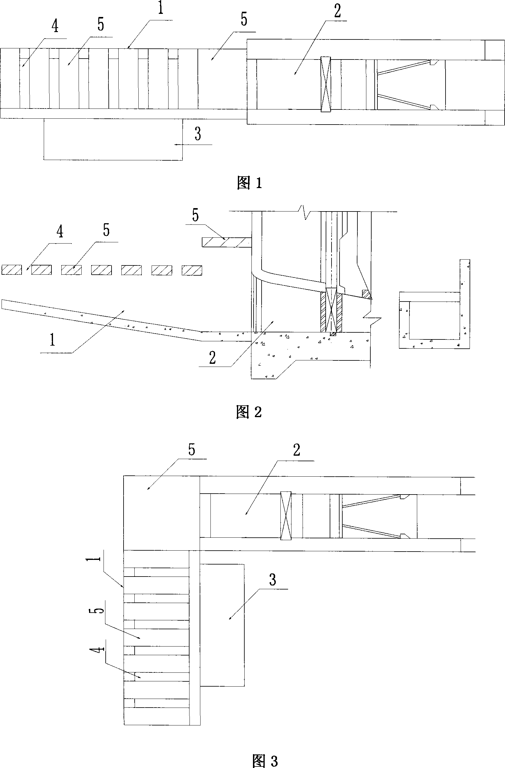
[0013] As shown in Figures 1 and 2, between the sand discharge bottom hole 2 and the water inlet 3 of the power station, a grid-type sand discharge corridor 1 is provided. The top of the corridor 1 is the grid gap 4 and the grid top plate 5, and the bottom is the bottom plate of the sand discharge corridor.

[0014] Also see Fig. 3, also has the same structure in this embodiment.

[0015] Engineering model test results

[0016] The river section where Project A is located is a sandy river. The average annual suspended sediment load at the dam site is 637,000 tons, and the transported sediment load is 191,000 tons. s =2.78t / m 3 , Silt dry bulk density γ s '=1.60t / m 3 , median diameter d 50 =33.3mm, average particle size d pj = 52.9 mm.

[0017] The project is a concrete gravity sluice dam (with flood discharge holes, sand bottom holes, and sewage channels), with a crest elevation of 2471.40m and a maximum dam height of 34.4m. The size of the flood discharge hole and the...


PUM


Abstract

The invention relates to a sand-discharge facility at a water inlet of a hydraulic power station, wherein the upper course or the lateral direction of a sand-discharging bottom hole (a sand flushing gateway) is provided with a grid-type sand-discharging gallery, and the basic body shape of the sand-discharging gallery is that the upper portion of a sand-sinking tank is provided with a grid-type top board. The sand-discharge facility at a water inlet of a hydraulic power station of the invention can achieve excellent sand-discharging effect.

Description

technical field [0001] The invention relates to a novel sand-discharging facility for removing sediment from a water inlet of a power station, and is especially suitable for a low-head river bed hub. Background technique [0002] On sandy rivers, whether it is a high-head power station or a low-head riverbed hub, the water intake and sediment discharge of the water inlet of the power station has always been a very important issue. For low-head riverbed hubs, a sand flushing tank (sand sedimentation basin) is usually installed in front of the water inlet of the power station, and sand removal bottom holes (sand flushing gates) are used to carry out sand removal. Due to the restriction of the flow rate of the flushing sand diversion, the range of the flushing funnel is small, and it is difficult to achieve the ideal sand discharge effect. Contents of the invention [0003] The purpose of the invention is to improve the sand discharge capacity of the facility by changing the...

Claims


Application Information

Patent Timeline
IPC IPC(8): E02B9/04E02B8/02
CPCY02E10/22Y02E10/20
Inventor 戴晓兵李延农
Owner POWERCHINA ZHONGNAN ENG
Why Eureka
Try Eureka