
A multi-stage pipeline automatic sand removal device with tree branch structure

An automatic drainage and pipeline technology, applied in water conservancy projects, marine engineering, coastline protection and other directions, can solve the problems of lack of comprehensiveness and systematization, and achieve the effect of significant sand drainage, energy saving and low cost.

Active Publication Date: 2018-06-29
BEIJING JIANGYI TECH
View PDF4 Cites 0 Cited by
  • Summary
  • Abstract
  • Description
  • Claims
  • Application Information

AI Technical Summary

Problems solved by technology

However, there is still a lack of comprehensive and systematic measures for the utilization of silt resources in reservoirs.

Method used


Image

  • A multi-stage pipeline automatic sand removal device with tree branch structure
  • A multi-stage pipeline automatic sand removal device with tree branch structure
  • A multi-stage pipeline automatic sand removal device with tree branch structure

Examples


Embodiment 1

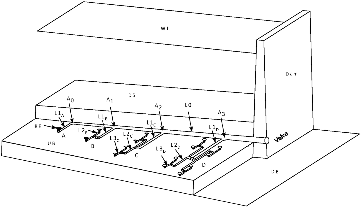
[0023] Embodiment one: lay out this device on the riverbed of the area in front of the dam of the reservoir (UB in the figure is the riverbed upstream of the reservoir, DB is the riverbed downstream of the reservoir, WL is the water surface), the overall layout is as follows figure 1 , the whole device of this embodiment is a tree branch structure arranged symmetrically, only the right half structure of the device is schematically drawn in the figure, and the left half structure is buried below the silted sand surface DS.

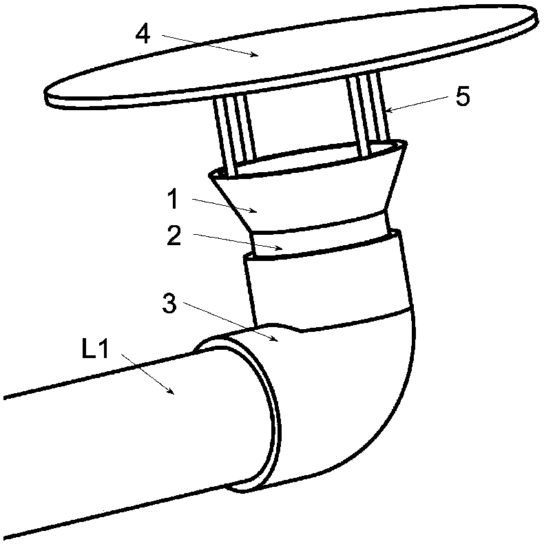
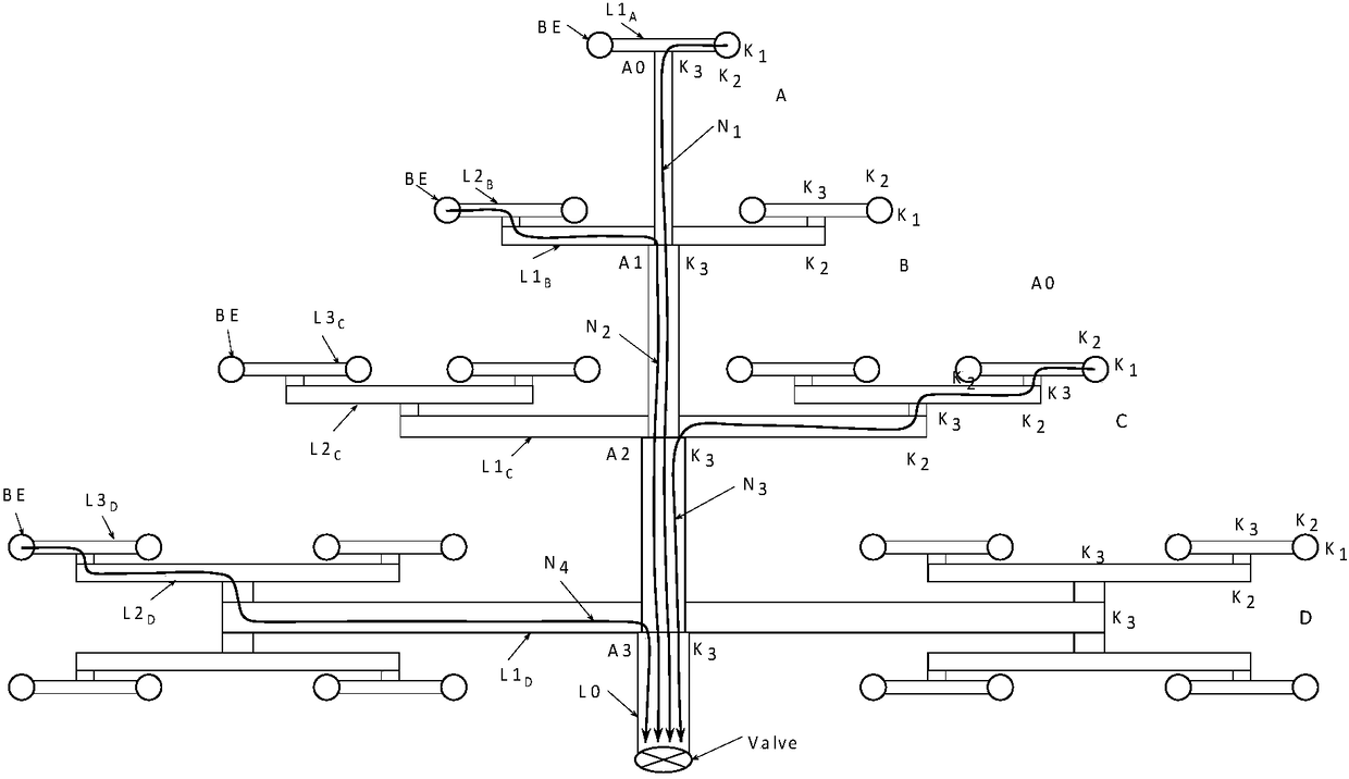
[0024] The main components of the device in this embodiment include multiple identical sand inlet heads BE, a branch structure multi-stage pipeline composed of the main sand delivery pipeline L0 and multi-level branch pipelines A, B, C, and D, and an outlet valve Valve; wherein, The main sand delivery pipeline L0 is arranged on the riverbed in front of the reservoir dam along the direction of water flow. There are two multi-level branch pipelines A, B, C, an...

Embodiment 2

[0058] Embodiment two: the overall structure of the sand discharge device of this embodiment is as follows Figure 4 As shown, the difference from the sand removal device described in Embodiment 1 is that the branch-structured multi-stage pipeline of this embodiment is composed of a main sand conveying pipeline L0 of equal cross-section and 3 groups of identical multi-level branch pipelines E, and 3 groups are more The first-level branch pipes E are arranged in a zigzag shape; each group of multi-level branch pipes E consists of the first-level branch pipes L1 E , 7 identical second-level branch pipelines L2 E , 14 identical third-level branch pipelines L3 E Composition, 7 second-level branch pipelines L2 E At common branch confluence port A 4Arranged in a circular divergence, and at the end of the branch confluence port and the first-level branch pipeline L1 E Connected, 14 tertiary branch pipes L3 E Evenly divided into 7 groups, each group has 2 third-level branch pipel...


PUM


Abstract

The invention relates to multistage pipeline automatic sand discharging device of a crotch structure and belongs to the field of hydraulic engineering operation management. The sand discharging device comprises multiple sand inlet heads, a multistage pipeline of a crotch structure, and an outlet valve, wherein the multistage pipeline is composed of a main sand conveying pipeline and a plurality of sets of multistage branch pipelines. The main sand conveying pipeline is arranged on a river bed of an area before a dam of a reservoir in the water flow direction. The confluence opening ends of all the multistage branch pipelines are connected with the main sand conveying pipeline, and the tail ends of all the multistage branch pipelines are connected with the sand inlet heads. The downstream end of the main sand conveying pipeline penetrates the bottom of the dam through the outlet valve. The multistage pipeline of the crotch structure meets the principle that loss of gross heads, converged to the outlet valve through the multistage pipeline of the crotch structure, of all the sand inlet heads is equal, so that upstream and downstream fall of the reservoir is utilized for carrying out automatic sand discharging. The device does not need additional power, saves energy, and is remarkable in economic benefit, safe, reliable, easy to operate and wide in application prospect.

Description

technical field [0001] The invention belongs to the technical field of operation management of water conservancy projects, and in particular relates to an automatic sand discharge device for multi-stage pipelines with a branch structure. Background technique [0002] The northwestern region of our country is seriously short of water, and the shortage of water resources is an important factor restricting the development of the national economy. However, most rivers with water shortages have high sediment content and coarse sediment particle size, which have adverse effects on various water conservancy engineering facilities. Small and medium reservoirs may lose their effectiveness due to silting within a few years; diversion canals often result in desertification of cultivated land due to silt deposits, such as the famous water diversion project "Zhengguo Canal" in history, which has been completely buried by silt deposits. [0003] For a long time, engineering design, manag...

Claims


Application Information

Patent Timeline
Patent Type & Authority Patents(China)
IPC IPC(8): E02B1/00E02B8/00
CPCE02B1/00E02B8/00
Inventor 王兴奎
Owner BEIJING JIANGYI TECH
Learn More