Buffer drive pole device

A technology of a transmission rod and a limiting part, which is applied in the field of a buffer transmission rod device, can solve problems such as easy damage, and achieve the effects of low cost, good two-way buffering, and easy promotion and implementation

Inactive Publication Date: 2008-05-28
赵建清
View PDF1 Cites 2 Cited by
  • Summary
  • Abstract
  • Description
  • Claims
  • Application Information

AI Technical Summary

Problems solved by technology

[0003] The purpose of the present invention is to provide a buffer type transmission rod device with simple structure, low cost and good buffering effect, so as to overcome the shortcoming of the traditional transmission rod that is easy to damage the product due to the transmission distance error

Method used


Image

  • Buffer drive pole device
  • Buffer drive pole device

Examples


Embodiment 1

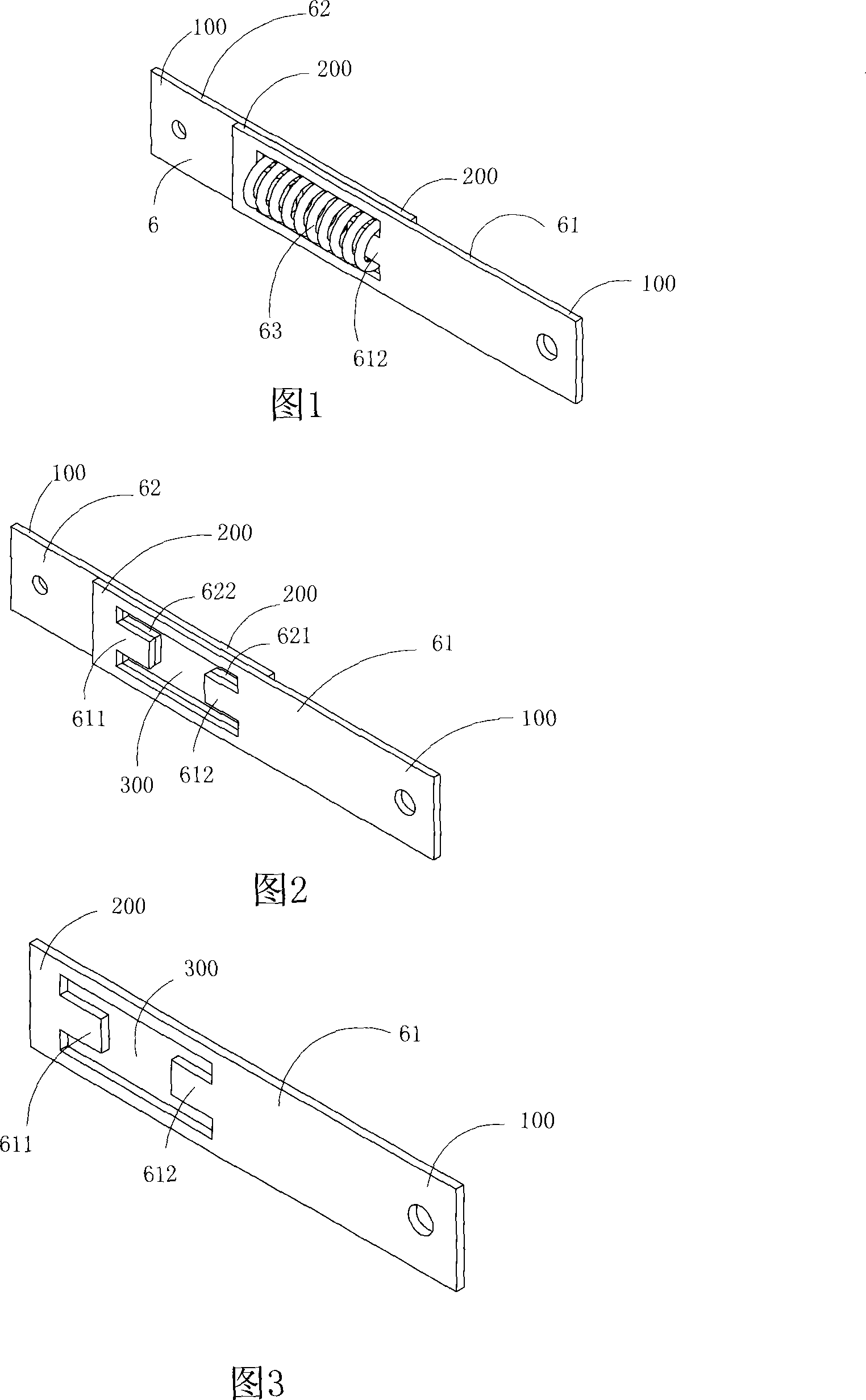
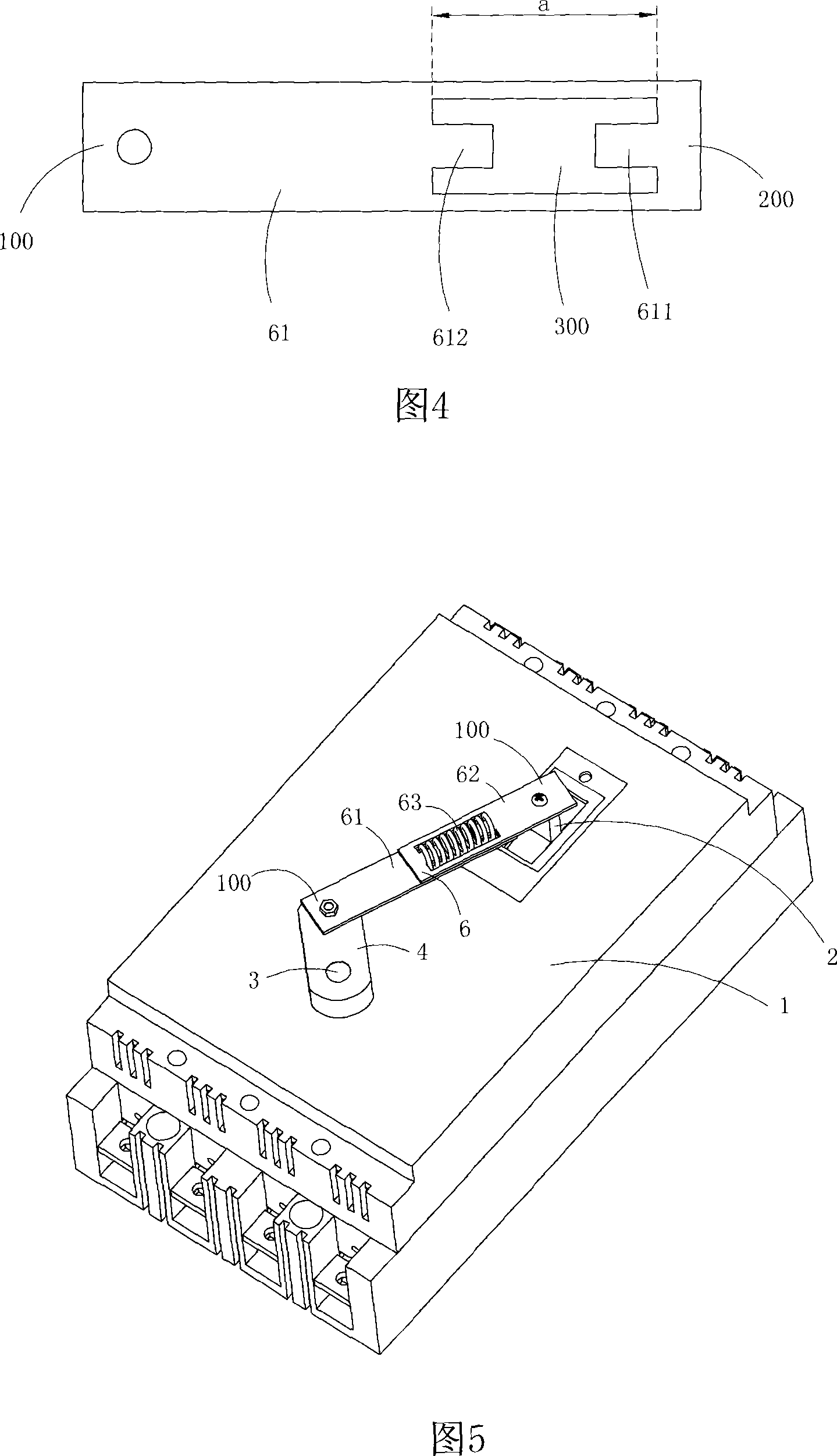
[0019] Figures 1 to 4 show the first embodiment of the present invention, wherein Figure 1 is a schematic diagram of a three-dimensional structure of the present invention; Figure 2 is a schematic diagram of a three-dimensional structure of the buffer transmission rod device shown in Figure 1 after the spring is removed ; FIG. 3 is a schematic diagram of the three-dimensional structure of the first transmission rod in the buffer transmission rod device shown in FIG. 1; FIG. 4 is a schematic diagram of the structure of the first transmission rod shown in FIG. 3 when viewed from the front.

[0020] This embodiment is a buffer transmission rod device, see Figures 1 to 4, the buffer transmission rod device 6 includes a first transmission rod 61, a second transmission rod 62 and an elastic member 63 for buffering; The first transmission rod 61 is provided with a first limiting portion 611 and a second limiting portion 612 for limiting the elastic member, and the second transmission ...

Embodiment 2

[0022] This embodiment is basically the same as Embodiment 1, except that the shapes of the first transmission rod 61 and the second transmission rod 62 are completely the same.

[0023] In summary, the present invention has the following advantages:

[0024] (1) The elastic member in the present invention can not only play the role of cushioning, but also can play the role of a coupler, which is used to connect two first transmission rods and second transmission rods arranged side by side. With its own restoring force, one end of itself is pressed against the first limit portion of the first transmission rod and the second limit portion of the second transmission rod, and the other end is pressed against the second limit portion of the first transmission rod. On the first limiting part of the upper part and the second transmission rod, choosing a spring with a suitable elastic force can realize the use effect of not only having a good two-way buffering effect, but also having...


PUM


Abstract

The invention discloses a cushioning type transmission rod device, which comprises elastic pieces, a first transmission rod and a second transmission rod, wherein, the elastic pieces are used for cushioning; the first transmission rod is provided with a first limited part and a second limited part which are used for limiting the elastic pieces. The second transmission rod is also provided with a first limited part and a second limited part which are used for limiting the elastic pieces. One end of the elastic pieces is abutted on the first limited part of the first transmission rod and the second limited part of the second transmission rod, and the other end is abutted on the second limited part of the first transmission rod and the first limited part of the second transmission rod. The invention has the advantages of simple structure, low cost and good cushioning effect, and effectively overcomes the shortcoming that the traditional transmission rod is easy to bring on damage to a product because of the error of a transmission distance.

Description

technical field [0001] The invention belongs to the technical field related to transmission rod structure, in particular to a buffer type transmission rod device. Background technique [0002] The power source often uses the transmission rod to drive the external device to move, for example, the cam mechanism drives the toggle switch or the operating handle of the circuit breaker through the transmission rod to realize the automatic operation of opening and closing. Generally speaking, it is necessary to control the moving distance of the transmission rod when the transmission rod is used for transmission, because when the transmission rod moves a large distance, the external device will be damaged due to excessive force. A device changes from one operating state to another. Therefore, a transmission rod with better cushioning effect is needed to overcome the shortcoming that the traditional transmission rod is easy to damage the product due to the error of the transmission...

Claims


Application Information

Patent Timeline
Patent Type & Authority Applications(China)
IPC IPC(8): H01H3/32H01H3/40H01H3/46
Inventor 赵建清
Owner 赵建清
Why Eureka
Try Eureka