Expanding type vertebral body shaper
A vertebroplasty and expansion technique, applied in the direction of fixator, internal fixator, internal bone synthesis, etc., can solve the problems of broken wire left, inconvenient operation, difficult extraction, etc.
- Summary
- Abstract
- Description
- Claims
- Application Information
AI Technical Summary
Problems solved by technology
Method used
Image
Examples
Embodiment 1
[0039] (Embodiment 1) Referring to Fig. 4 and Fig. 5, the expandable vertebral body shaper of this embodiment includes a mandrel 1, a push tube 2 and a distraction ball 3.
[0040] The mandrel 1 includes a mandrel body 11 and a fixing column 12 that is clipped on the right end of the mandrel body 11 . The mandrel main body 11 is a steel wire. The fixing column 12 is provided with an annular groove 12-1 along the circumferential direction.
[0041] The push tube 2 includes a push tube main body 21 and two bumps 22. The push tube main body 21 is a hollow steel pipe, and the two bumps 22 are symmetrically arranged, and are divided into a front bump 22-1 and a rear bump 22-2. The block 22 - 1 is fixedly connected to the push tube main body 21 from the front, and the rear projection 22 - 2 is fixedly connected to the push tube main body 21 from the rear, and both are located on the right side of the push tube main body 21 . The push tube 2 is sleeved on the mandrel body 11 of the...
Embodiment 2
[0045] (Embodiment 2) Referring to FIG. 6 , the rest of the expandable vertebroplasty device of this embodiment is the same as that of Embodiment 1, except that a protective sheath 6 is also included. The protective cover 6 includes a sleeve 63 and a latex cover 64 . The casing 63 is a horizontal hollow circular tube, slightly thicker than the push tube 2 . The left end of latex sleeve 64 seals and opens to the right, and latex sleeve 64 is coated on the outside of sleeve pipe by its right section, and the left section of latex sleeve 64 is positioned at the left side of the left end of sleeve pipe 63, becomes and can be elastically supported from the inside. Open latex head 64-1.
[0046] When the expansion-type vertebroplasty device of this embodiment is in use, the push tube 2 together with the mandrel 1 and the expanded ball 3 are inserted into the sleeve 63 of the protective sleeve 6 from right to left, and the expanded ball 3 The left section then stretches in the late...
Embodiment 3
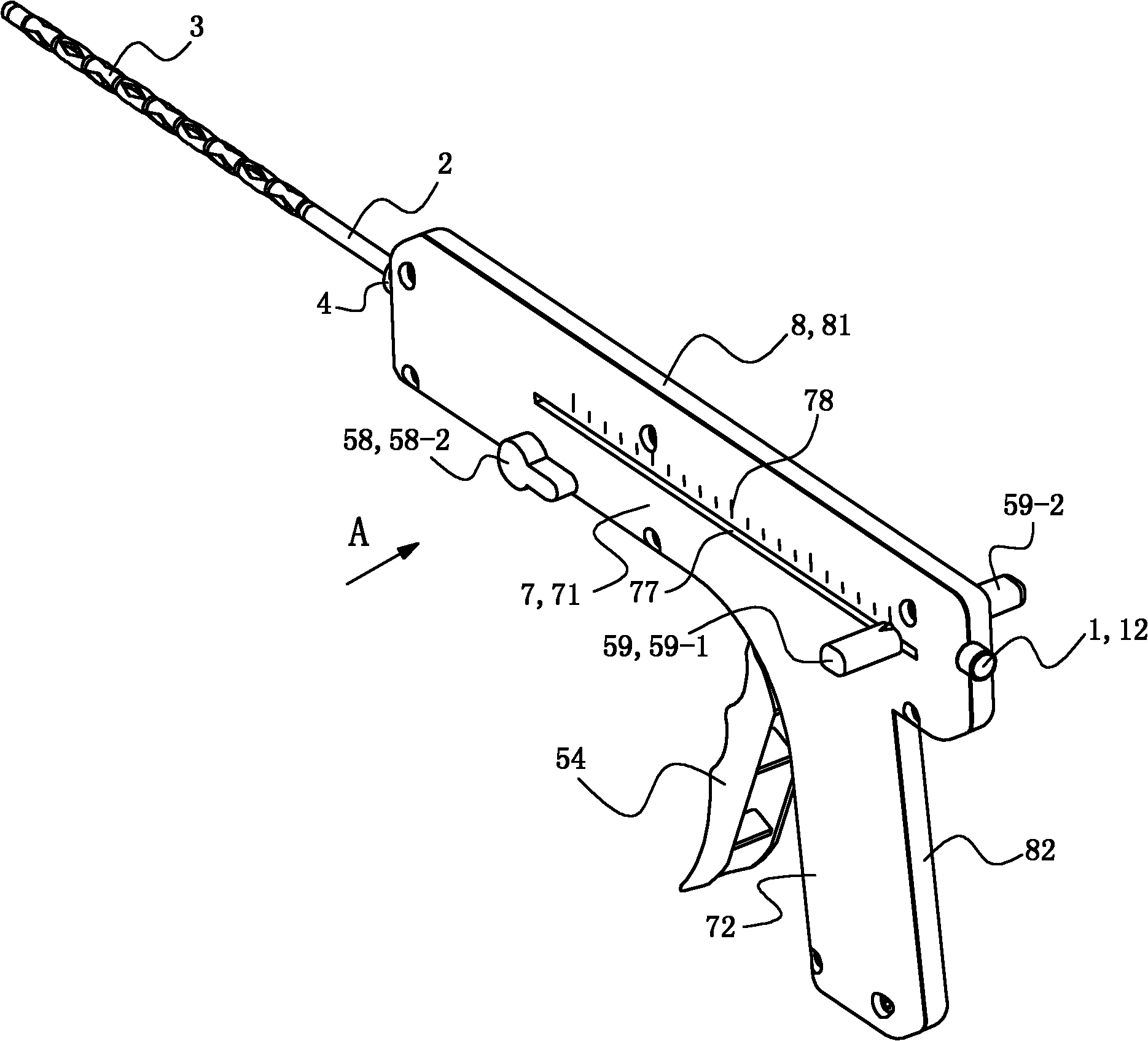
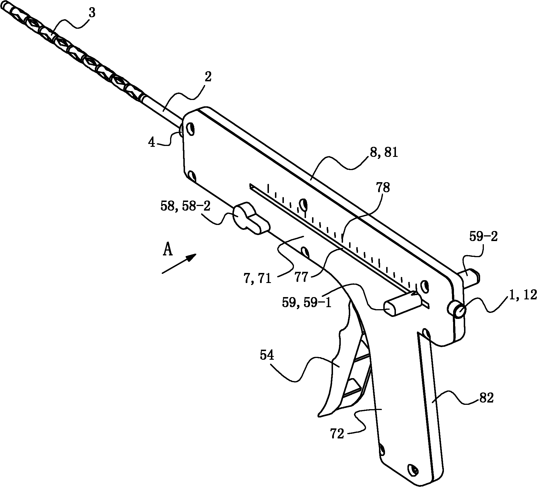
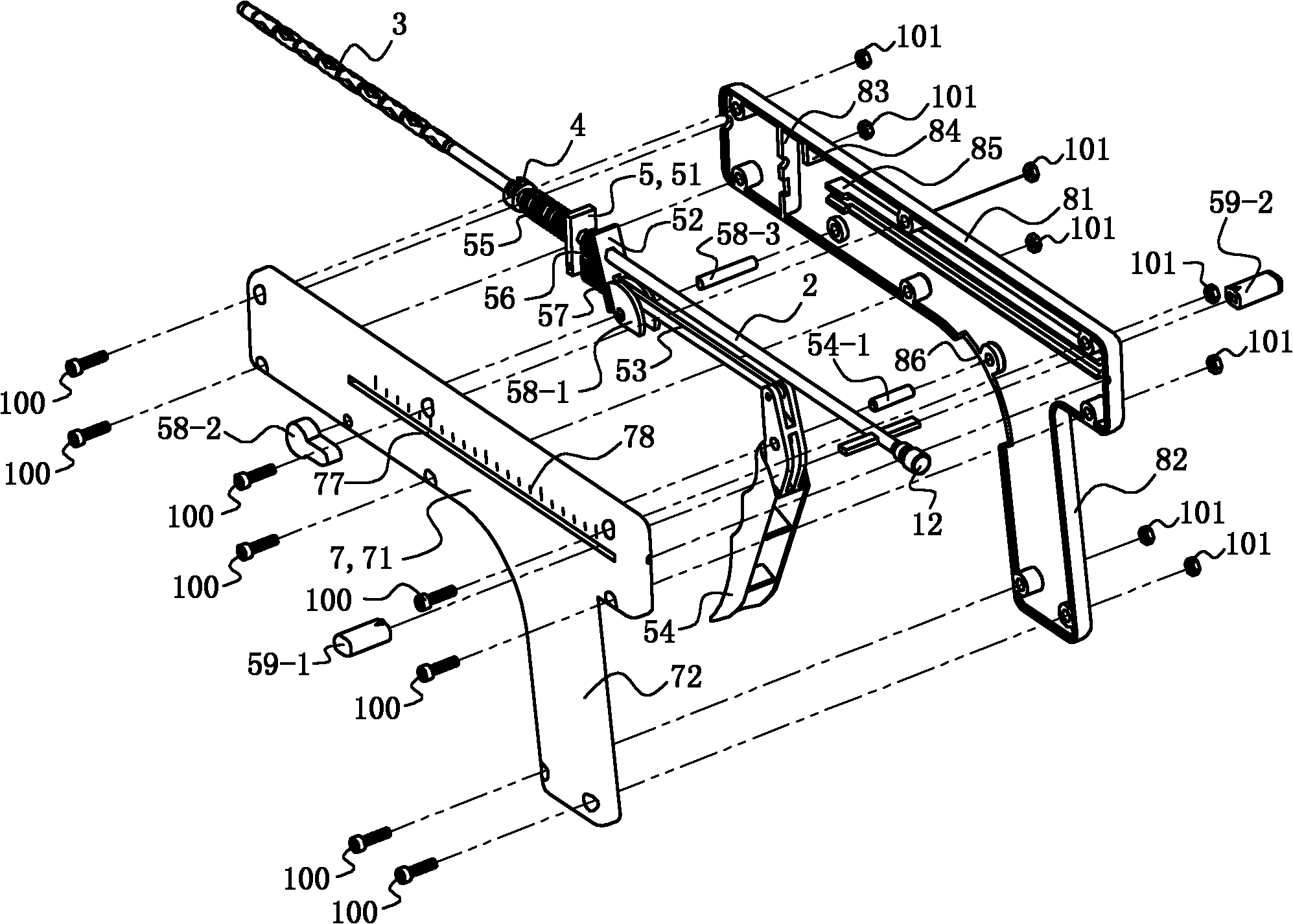
[0047] (Embodiment 3) Referring to Fig. 1 , the expansion type vertebroplasty device of this embodiment includes a mandrel 1, a push tube 2, a distraction ball 3, a fixed ring 4, a control assembly 5 and a housing.
[0048] 2 and 3, the housing includes a front housing 7 and a rear housing 8. Both the front housing 7 and the rear housing 8 are injection-molded integral parts, and the structures of the two are basically symmetrical.
[0049] The front casing 7 includes a front casing main body, a left front baffle 73 , a right front baffle 74 and two front limit stops 75 . The front shell body includes a front shell gun handle 71, a front shell gun handle 72 connected to the lower right side of the front shell gun handle 71, and a front shell on the left side at the junction of the front shell gun handle 71 and the front shell gun handle 72. The handle groove 76, the elongated front hole 77 provided on the front shell gun shaft portion 71 and the front shell scale 78 located on...
PUM
 Abstract
Description
Claims
Application Information
 - R&D
- Intellectual Property
- Life Sciences
- Materials
- Tech Scout
- Unparalleled Data Quality
- Higher Quality Content
- 60% Fewer Hallucinations
Browse by: Latest US Patents, China's latest patents, Technical Efficacy Thesaurus, Application Domain, Technology Topic, Popular Technical Reports.
© 2025 PatSnap. All rights reserved.Legal|Privacy policy|Modern Slavery Act Transparency Statement|Sitemap|About US| Contact US: help@patsnap.com


