
Device for cleaning subsea surfaces such as ship hulls

a technology for cleaning devices and hulls, applied in the direction of electrostatic cleaning, waterborne vessels, movable spraying apparatus, etc., can solve the problems of increasing fuel consumption, requiring rather frequent cleaning, and reducing the life of components, so as to achieve optimal cleaning effect, reduce rotational speed, and improve the effect of li

Inactive Publication Date: 2010-04-20
CLEANHULL NORWAY
View PDF14 Cites 6 Cited by
  • Summary
  • Abstract
  • Description
  • Claims
  • Application Information

AI Technical Summary

Benefits of technology

[0018]It is a further object of the invention to provide a device as mentioned above, that is able to clean surfaces treated with paint / ship-bottom paint, without inflicting measurable damages to the paint / ship-bottom paint and thereby inflicting an undesired strain on the environment.
[0020]It is a further object of the invention to provide a device for effective cleaning of fouled or heavy contaminated surfaces by applying water under pressure, b which the cleaning effect in a simple manner may be optimized for a certain water pressure.
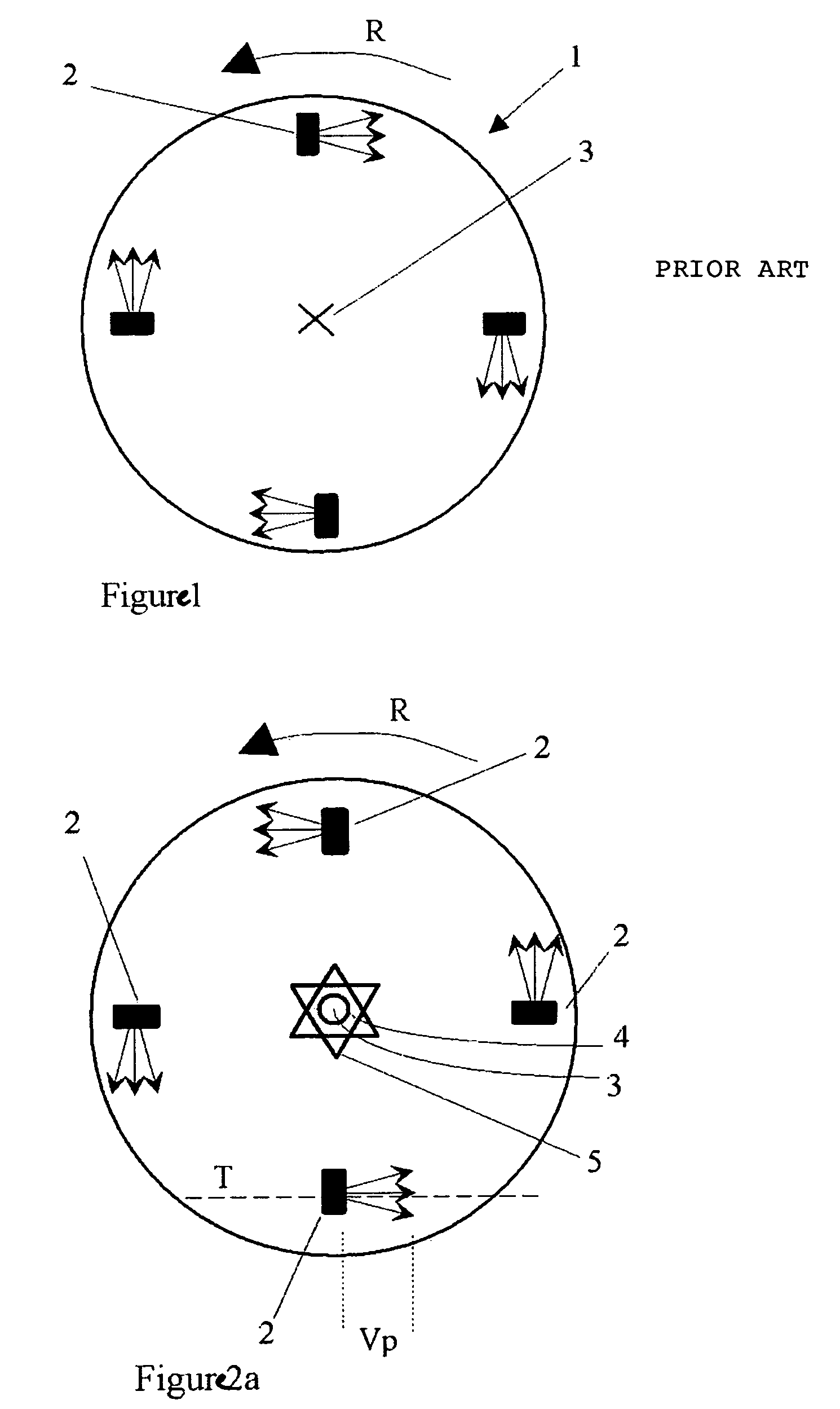
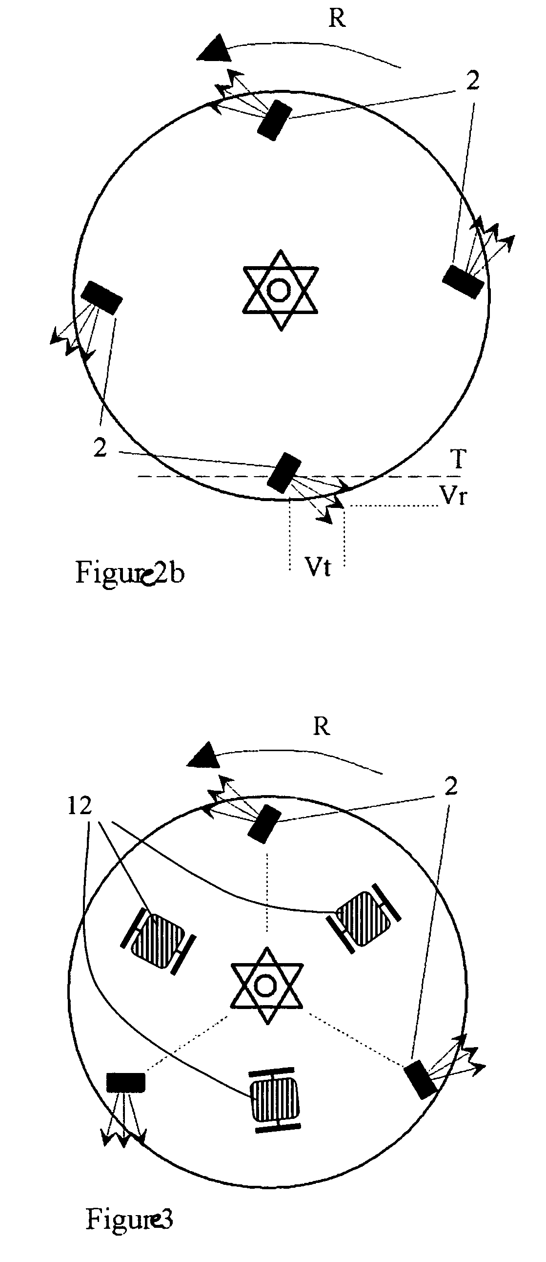
[0027]An additional advantage of the device according to the invention is the occurrence of a strong suction force between the rotation member, or more precisely the central areas of this, and the surface to be cleaned. This suction force completely counteracts the “recoil” of the water being discharged from the cleaning nozzles at high speed. Thus it is not required to use extra energy to hold the device closely adjacent to e.g. a ship hull when it is cleaned.

Problems solved by technology

It is a considerable challenge to develop equipment for large surfaces such as ship hulls, partly due to their limited availability being partly submerged in water.
On the other hand, due to fouling of the surfaces with marine organisms that make the surfaces rough and not smooth, a rather frequent cleaning is required.
A ship hull covered with layers of such organisms will have a significant increase in fuel consumption as a result of the increased friction between the hull and the water.
In this connection it should be noted that an increase in friction of 1% leads to an increase in fuel consumption of 3%.
Furthermore ship hulls are commonly coated with toxic ship-bottom paints containing organic tin compounds that it is highly desired remain in place during the cleaning operation, as it else will lead to poisoning of marine organisms.
It is thus a challenge to develop equipment that removes impurities from the surfaces but that does not or to only a limited extent damage any layers of ship-bottom paints present.
The apparatus according to this US patent is not suited for cleaning surfaces under water, since the rotating arms provided with nozzles are localized in a substantially open construction and would be surrounded by water that would drastically reduce the arms ability to rotate if the apparatus is submerged in water.
It is a significant challenge to provide a sufficient cleaning of fouled surfaces of a ship hull without damaging or removing parts of the ship-bottom paints applied to the hull.
At the same time it is a considerable challenge when transferring liquid under high pressure to a high-speed rotation disc or the like, to establish a liquid coupling that is reliable and leakage free over a longer period of time.

Method used


Image

  • Device for cleaning subsea surfaces such as ship hulls
  • Device for cleaning subsea surfaces such as ship hulls
  • Device for cleaning subsea surfaces such as ship hulls

Examples


example

[0049]Cleaning were performed on test surfaces treated with a tributyltin (TBT) containing antifouling agent. In connection with performance of the tests water to the cleaning nozzles was recycled from / to test vessels, so that dilution of any organic compound introduced in the vessels were avoided. The operation of the rotary discs was however made in another manner which implied a dilution of all concentrations in the vessel by 12 l / minute. This effect, however, only had a 0.35% impact for first test sample and a 1.7% impact for second and third test sample. The test was conducted as shown by table 1 below.

[0050]

TABLE 1Point intimeSampleActivityRemarks4 / Oct-02Positioning of sample plates in test vessel filledwith fresh water (1170 litres). A number of 10 steelplates treated with TBT containing anti-fouling4-7 / Oct-02Leakage of organic tin compounds to water in testvessel7 / Oct-02Sample 1Sample of water in test(kl 10:00)vessel subsequentleakage but prior tofirst cleaning7 / Oct-02Cleani...


PUM


Abstract

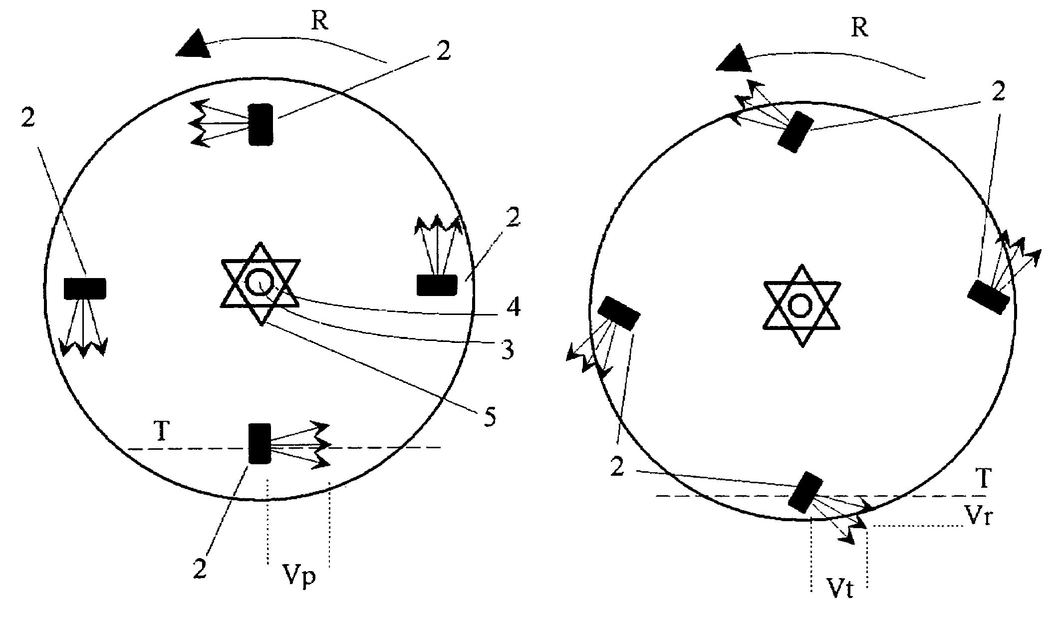
Device for cleaning of surfaces under water, such as ship hulls, includes a rotary disc furnished with nozzles for discharge of pressurized liquid against the surface to be cleaned. The nozzles are mounted obliquely in relation to the rotational axis of the rotary disc and are arranged to be supplied with pressurized liquid through a hollow spindle that is concentric with the rotational axis. The nozzles have an inclination that have an orientation involving that the velocity component (Vp) of the liquid jet from each nozzle that is not perpendicular to the surface to be cleaned, has a tangential velocity component (Vt) that has the same direction as the direction of rotation (R) of the rotary disc and optionally a radial velocity component that is positive, i.e. that is directed outwards in relation to the center of the disc.

Description

[0001]This application is a filing under 35 USC 371 of PCT / NO2004 / 000339, filed Nov. 10, 2004.BACKGROUND OF THE INVENTION[0002]The present invention concerns a device for cleaning surfaces, particularly large surfaces that have at least partly limited availability for conventional methods of cleaning, including ship hulls and the like.[0003]It is a considerable challenge to develop equipment for large surfaces such as ship hulls, partly due to their limited availability being partly submerged in water. On the other hand, due to fouling of the surfaces with marine organisms that make the surfaces rough and not smooth, a rather frequent cleaning is required. A ship hull covered with layers of such organisms will have a significant increase in fuel consumption as a result of the increased friction between the hull and the water. In this connection it should be noted that an increase in friction of 1% leads to an increase in fuel consumption of 3%.[0004]Furthermore ship hulls are common...

Claims


Application Information

Patent Timeline
Patent Type & Authority Patents(United States)
IPC IPC(8): B08B3/02B63B59/08
CPCB63B59/08B08B3/024B63B59/00B08B3/02
Inventor ANDERSEN, ROBERTSPERRE, THOR OLAY E.
Owner CLEANHULL NORWAY
Learn More