Covering stripping device for covered electric cable

A technology for covering wires and coating layers, which is applied in the direction of line/collector parts, circuits, electrical components, etc., and can solve problems such as broken wires, scratches from wire coating strippers, and uncoated wires.

Inactive Publication Date: 2011-02-16
CHUBU ELECTRIC POWER CO INC +1
View PDF5 Cites 0 Cited by
  • Summary
  • Abstract
  • Description
  • Claims
  • Application Information

AI Technical Summary

Problems solved by technology

Solve the technical problem that the exposed wires are easily damaged by the coating stripper, which leads to disconnection
Solve the technical problem that the stripping operation of curved covered wires cannot be smoothly performed

Method used


Image

  • Covering stripping device for covered electric cable
  • Covering stripping device for covered electric cable
  • Covering stripping device for covered electric cable

Examples


Embodiment Construction

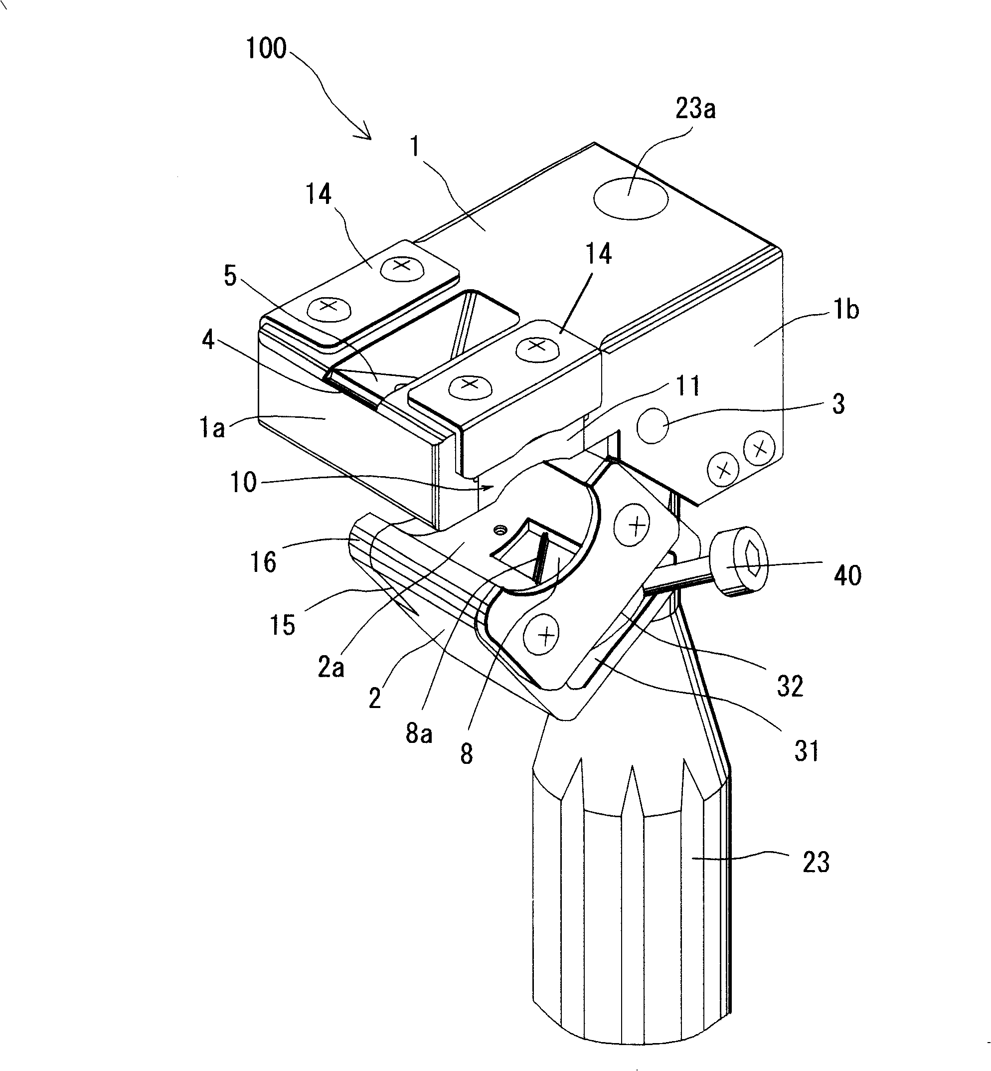
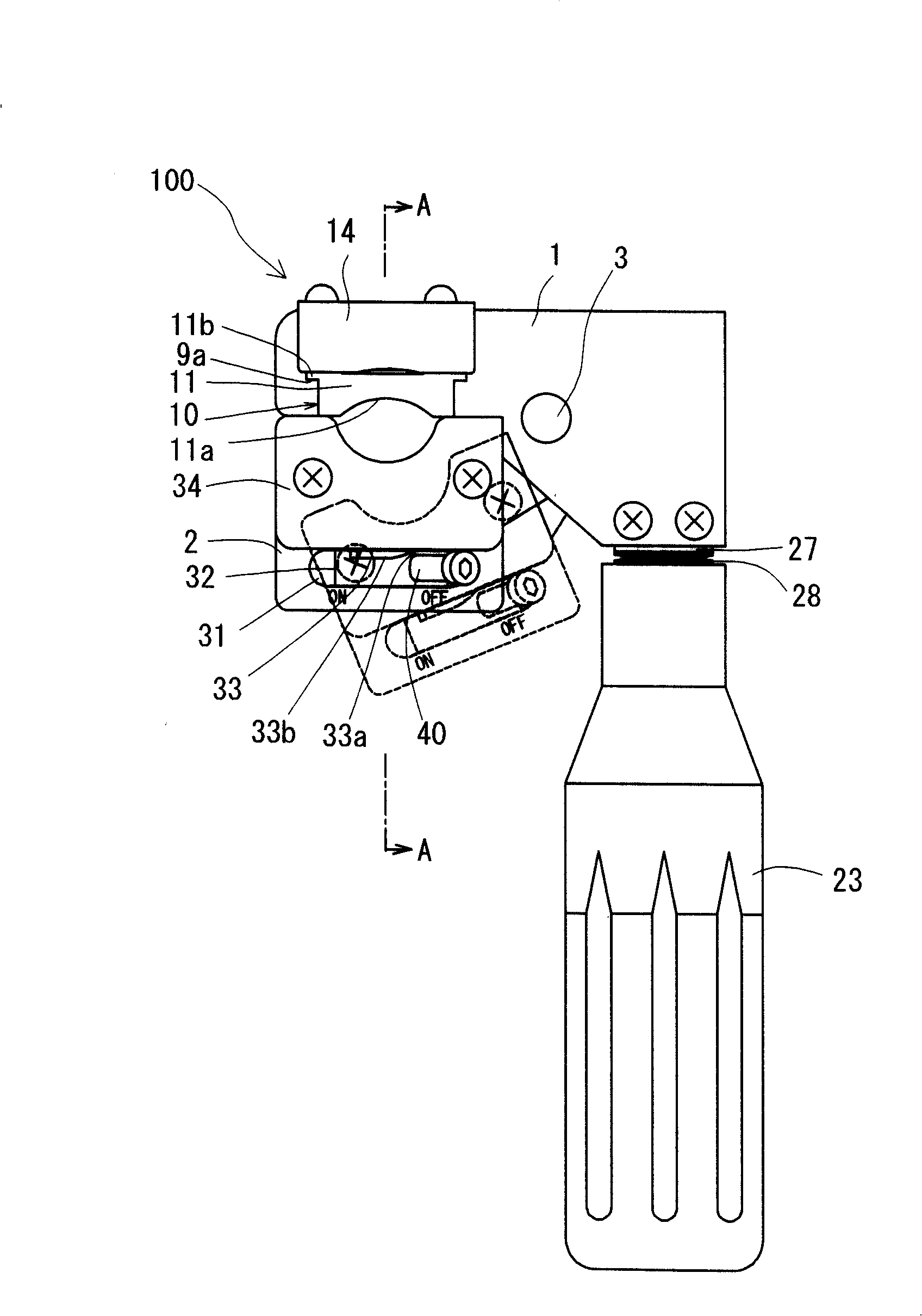
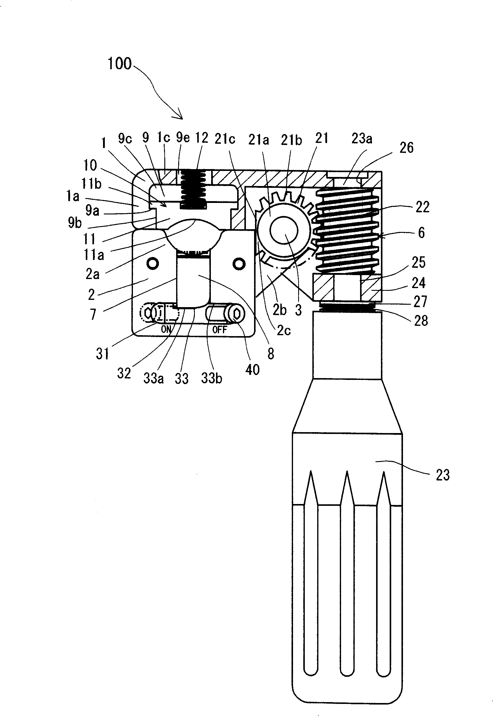
[0037]Covered electric wire coating stripper 100 of the present invention comprises: clamping part body 1, has one side clamping part 1a that clamps covered electric wire D; The clamping part 1a jointly clamps the other side clamping part 2a of the coated wire, and is supported on the clamping part body 1 in a freely rotatable manner through the shaft, and at the same time, the other side clamping part 2a can approach or leave the clamp. Rotate in the direction of the one side clamping portion 1a of the clamping component body 1; the cutter 5 for peeling off the cladding layer is arranged at the near center of the one side clamping portion 1a of the clamping component body 1; the operating mechanism 6 is used to rotate The movable clamping member 2 rotates relative to the covered electric wire D in a state of clamping the covered electric wire D so that the covering layer H can be peeled off by the cutter 5 for peeling off the covering layer. Then, the coated electric wire coa...


PUM


Abstract

The invention relates to a clad detacher for covering wire which is used for resolving the technical problem that the clad detacher is easy to bump the wire and the bending covering wire can not be peeled off. The detacher comprises a holding part body, a movable holding part supporting at the holding part body rotatablely freely through the an axle and rotating near or away from the direction ofthe holding part body, a cutter for clad detacher located almost the center of the holding part body, an operating mechanism for rotating the movable holding part. Under the state of holding the cladwire, through the rotation corresponding to the clad wire, the clad is peeled off with the cutter for clad detacher. In the mean time of peeling off the clad, the clad detacher for covering wire can travel along the axial direction of the covering wire. The holding part body is also provided with a wire pressing mechanism which can approach the covering wire after the uncovering of the clad. The obtained detacher can avoid bumping the exposed wire as well as peel off the bending covering wire actually.

Description

technical field [0001] The present invention relates to a coated wire coating stripper for stripping an insulated wire coating layer of a high voltage coated wire or the like. Background technique [0002] Conventionally, when the covered wire of a high-voltage electric wire is introduced into an inverter for connection, etc., it is necessary to use a wire coating stripper to peel off the coating layer of the covered wire. As a conventional electric wire coating stripper, its structure is: relative to the fixed side clamping part that clamps the coated wire, the movable side clamping part is supported by the supporting shaft in the state of opening and closing, and the operating handle When the cam plate is operated, the elastic pressing plate equipped on the movable side clamping part is lifted up by the cam plate, so that the movable side clamping part is closed to the fixed side clamping part. In addition, the coated wire coating layer stripper also has: a guide tool wit...

Claims


Application Information

Patent Timeline
Patent Type & Authority Patents(China)
IPC IPC(8): H02G1/12H01R43/28
Inventor 加藤诚二大桥徹柴田光彦
Owner CHUBU ELECTRIC POWER CO INC
Why Eureka
Try Eureka