Sealing device

A sealing device and sealing ring technology, applied in the direction of engine sealing, engine components, mechanical equipment, etc., can solve problems such as breakage, deformation, damage to the peripheral sealing lip 102, etc., to improve sealing performance, excellent sealing performance, prevent damage effect

Inactive Publication Date: 2008-05-28
NOK CORP
View PDF0 Cites 8 Cited by
  • Summary
  • Abstract
  • Description
  • Claims
  • Application Information

AI Technical Summary

Problems solved by technology

[0008] However, in the conventional sealing apparatus 100 shown in FIG. risk of damage
In order to avoid damage, when the above-mentioned outer peripheral sealing lip 102d is molded in the opposite direction in the axial direction, after the mounting ring 101 is integrally formed with the first sealing ring 102, it is difficult to demould, so the During the process, the outer peripheral sealing lip 102d will have relatively large deformation between the mold (not shown in the figure) that moves its inner periphery and the cylindrical portion 101b of the outer periphery of the mounting ring 101, and there is a risk of damage

Method used


Image

  • Sealing device
  • Sealing device
  • Sealing device

Examples


Embodiment Construction

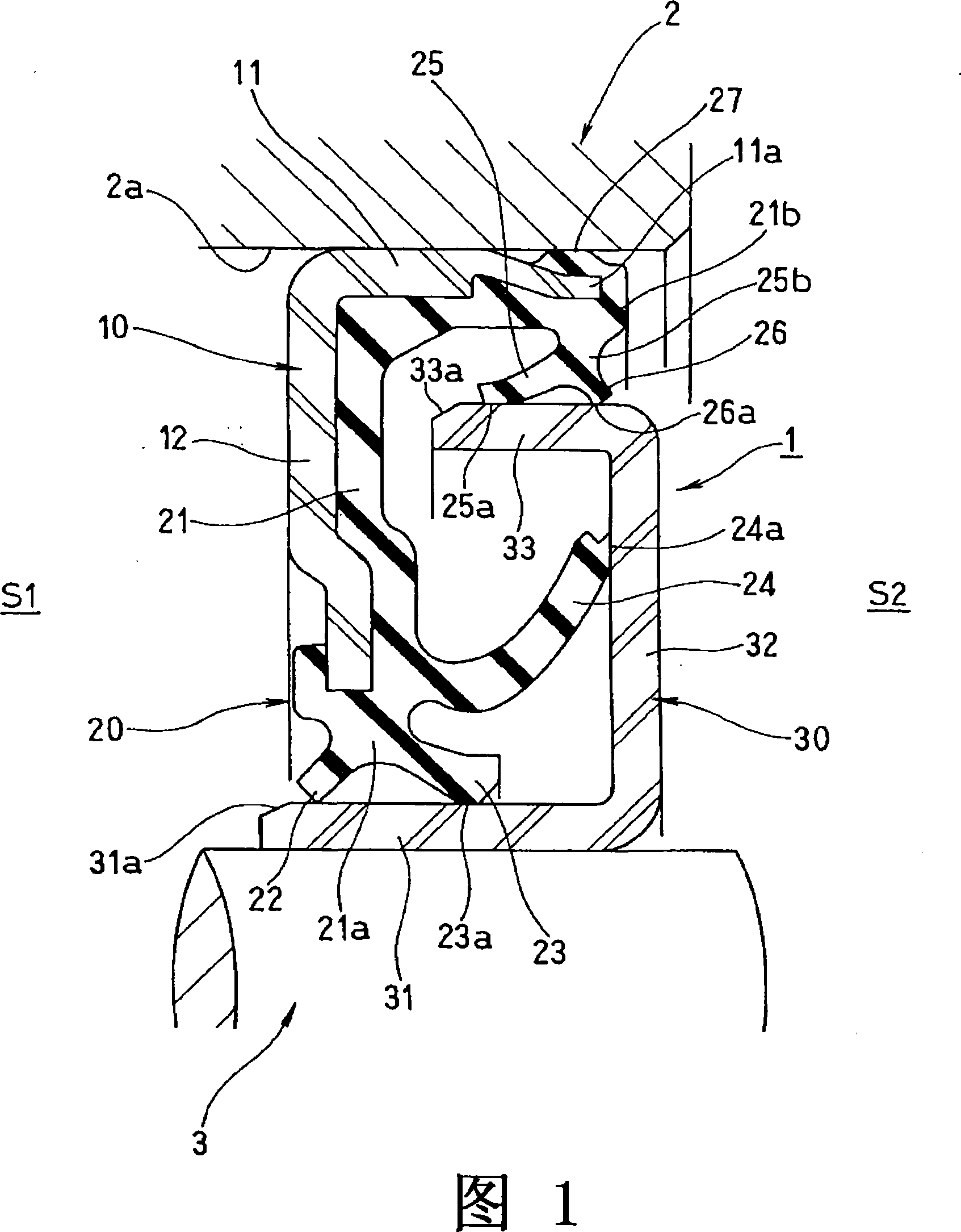
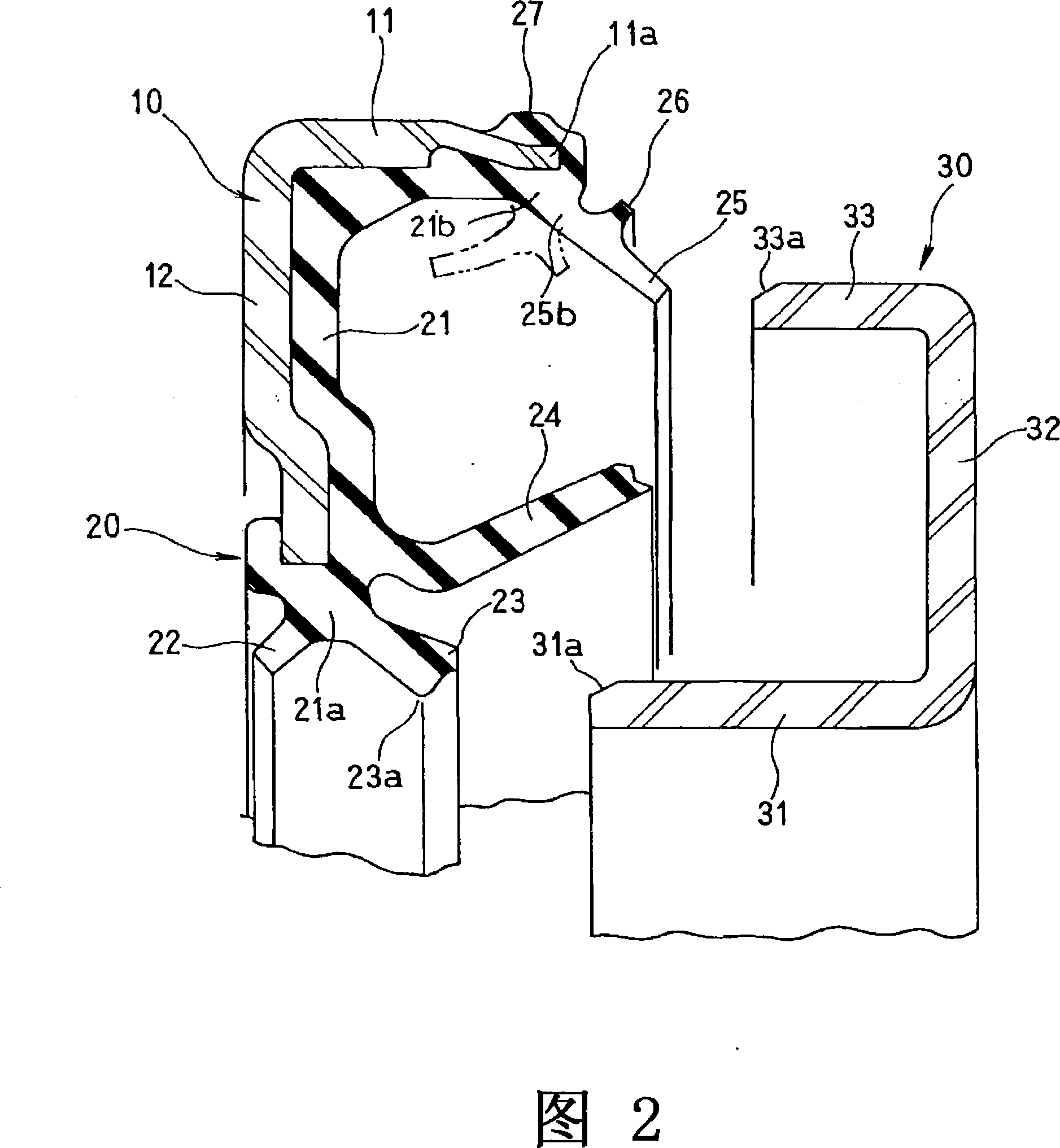
[0042] Preferred embodiments of the sealing device according to the present invention will be described below with reference to the accompanying drawings. First of all, Fig. 1 is a half-sectional view showing that the sealing device according to the present invention is cut by a plane passing through the axis, and Fig. 2 is a half-sectional view showing that the sealing device according to the present invention is also cut by a plane passing through the axis. A half-sectional view of the first sealing ring and the second sealing ring in a separated state.

[0043] In Fig. 1, symbol 1 is the sealing device according to the present invention, 2 is the outer peripheral side parts (such as the bearing outer ring in the running parts of automobiles or agricultural machinery, construction machinery), and 3 is the inner peripheral side parts (such as the above-mentioned bearings) inner circle). The sealing device 1 is composed of a mounting ring 10 mounted on the outer peripheral me...


PUM


Abstract

A sealing device where a seal lip (25) of a first seal ring (20) integrally formed with an installation ring (10) from a rubber-like elastic material is made to be slideably in intimate contact with a second seal ring (30) on the inner periphery side of the lip. Degradation in sealing ability of the device caused by reversing of the lip (25) when the second seal ring (30) is installed is prevented, parting of the first seal ring (20) from a mold after molding is facilitated, and the degree of freedom of setting the thickness of the seal lip (25) is increased. To achieve this, the sealing device has the first seal ring (20) integrally formed with the installation ring (10) from a rubber-like elastic material and also has the second seal ring (30) combined with the first seal ring (20), the first seal ring (20) has the seal lip (25) formed projecting outward from the tip (11a) of a tube section (11) of the installation ring (10), and the seal lip (25) is made to be slideably in intimate contact with the outer peripheral surface of the second seal ring (30), with the seal lip (25) reversed toward the inner periphery of the tube section (11) by insertion of the second seal ring (30).

Description

technical field [0001] The present invention relates to a sealing device for preventing the intrusion of dust, muddy water and the like into bearing parts and the like in running parts of, for example, automobiles or agricultural machinery and construction machinery. Background technique [0002] A typical prior art of such a sealing device is disclosed in, for example, Patent Document 1 below. [0003] Patent Document 1: Publication No. 7-40127 [0004] FIG. 3 is a cross-sectional view showing the conventional sealing device described in Patent Document 1 taken along a plane passing through the axis. In this FIG. 3 , reference numeral 110 is an outer peripheral part (such as an outer ring of a bearing), 120 is an inner peripheral part (such as an inner ring of a bearing), and the sealing device 100 is installed between the outer peripheral part 110 and the inner peripheral part 120 between. [0005] Specifically, the sealing device 100 includes a metal mounting ring 101 ...

Claims


Application Information

Patent Timeline
Patent Type & Authority Applications(China)
IPC IPC(8): F16J15/32F16J15/3232F16J15/3256
CPCF16J15/3264F16J15/32
Inventor 神前刚松井宏树小林直人山中聪
Owner NOK CORP
Why Eureka
Try Eureka