LCD device

A liquid crystal display device and liquid crystal technology, applied in static indicators, optics, instruments, etc., can solve problems such as insufficient temperature compensation function, and achieve the effect of improving the display effect of the screen

Inactive Publication Date: 2008-06-04
INNOCOM TECH (SHENZHEN) CO LTD +1
View PDF0 Cites 6 Cited by
  • Summary
  • Abstract
  • Description
  • Claims
  • Application Information

AI Technical Summary

Problems solved by technology

[0008] In order to solve the defect that the temperature compensation function of the existing liquid crystal display device is not in place, it is necessary to provide a liquid crystal display device that can automatically adjust the driving voltage according to the change of the physical properties of the liquid crystal at different temperatures

Method used


Image

  • LCD device
  • LCD device
  • LCD device

Examples


Embodiment Construction

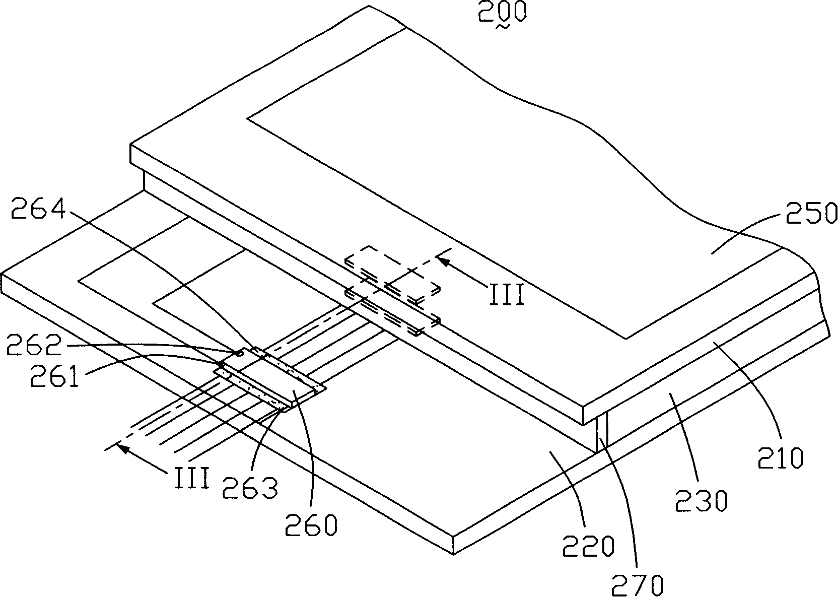
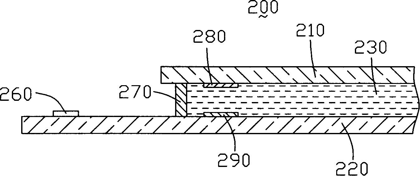
[0014] Please also refer to figure 2 with image 3 ,in figure 2 is a three-dimensional structure diagram of a liquid crystal display device disclosed in a preferred embodiment of the present invention, image 3 yes figure 2 A schematic cross-sectional view of the liquid crystal display device shown along line III-III. The liquid crystal display device 200 includes a first substrate 210 , a second substrate 220 , a liquid crystal layer 230 , a driver 260 , a frame glue 270 , a first sensing electrode 280 and a second sensing electrode 290 .

[0015] Both the first substrate 210 and the second substrate 220 are flat, and the second substrate 220 has an extension relative to the first substrate 210 .

[0016] The liquid crystal layer 230 is disposed between the first substrate 210 and the second substrate 220 , and the liquid crystal layer 230 is surrounded by the sealant 270 . The main material of the sealant 270 is a one-component heat-responsive resin, and the resin co...


PUM


Abstract

The present invention provides a liquid crystal display device, comprising a first basal plate, a second basal plate arranged opposite to the first basal plate, a liquid crystal layer clamped between the first basal plate and the second basal plate, an electrical resistivity induction device arranged between the first basal plate and the second basal plate, and a driver connected with the electrical resistivity induction device. The driver outputs driving voltage to drive the liquid crystal display device. The electrical resistivity induction device detects the electrical resistivity of liquid crystal. The driver adjusts the driving voltage according to the detected liquid crystal electrical resistivity.

Description

technical field [0001] The invention relates to a liquid crystal display device. Background technique [0002] Liquid crystal display (Liquid Crystal Display, LCD) has gradually replaced the traditional cathode ray tube (Cathode Ray Tube, CRT) display device due to its advantages of light weight, low power consumption, no radiation and portability, and is widely used in modern Information equipment, such as monitors, televisions, mobile phones and digital products. [0003] The physical properties of liquid crystal molecules are easily affected by temperature. When the temperature changes, the deflection characteristics of the liquid crystal molecules according to the applied electric field will be affected. For example, at low temperatures, the liquid crystal molecules will not rotate rapidly, resulting in a longer response time of the liquid crystal display device, and the rotation of the liquid crystal molecules will not be in place. The contrast of the display device d...

Claims


Application Information

Patent Timeline
Patent Type & Authority Applications(China)
IPC IPC(8): G02F1/133G09G3/36
CPCG09G2320/0252G09G2300/0408G02F2203/60G09G2320/041G09G3/3685G09G2300/0426
Inventor 徐伟初
Owner INNOCOM TECH (SHENZHEN) CO LTD
Why Eureka
Try Eureka