Device and method for multiparametric analysis of microscopic elements

A technique of microelement and equipment, applied in the field of microelement analysis

Inactive Publication Date: 2008-06-04
HORIBA ABX SAS
View PDF3 Cites 11 Cited by
  • Summary
  • Abstract
  • Description
  • Claims
  • Application Information

AI Technical Summary

Problems solved by technology

[0021] A limitation of compensation is that its criticality increases with the number of fluorochromes, which is related to the spread and amplification of the noise in the fluorescence measurements and the linear combination of the fluorescence measurements used to correct the raw measurements

Method used


Image

  • Device and method for multiparametric analysis of microscopic elements
  • Device and method for multiparametric analysis of microscopic elements
  • Device and method for multiparametric analysis of microscopic elements

Examples


Embodiment Construction

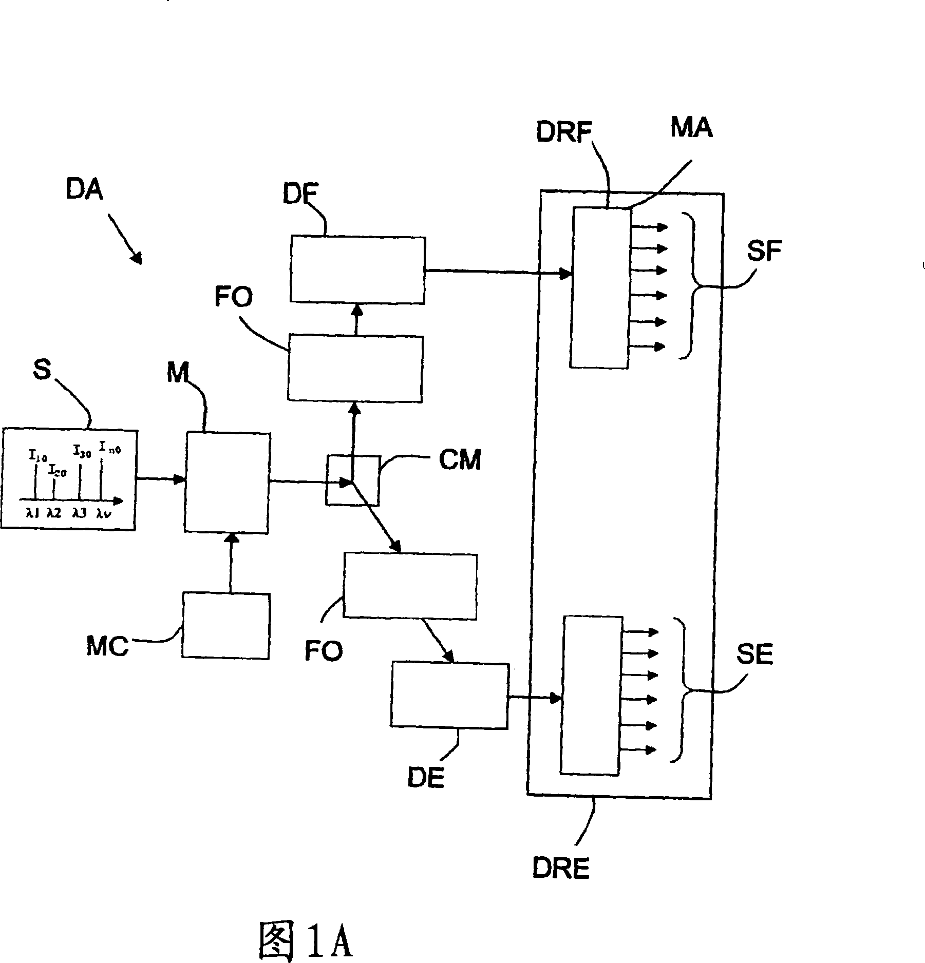
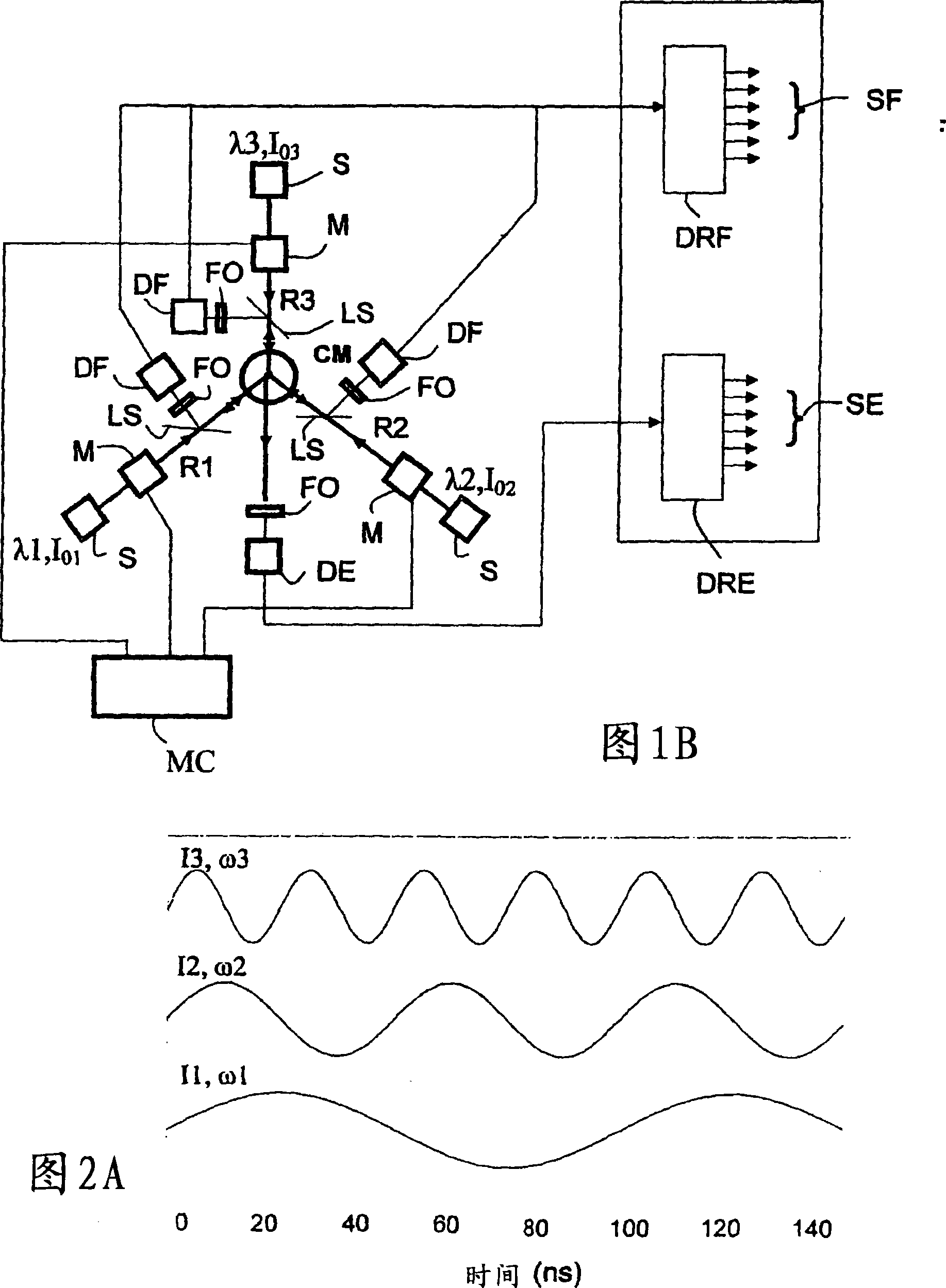
[0068] Referring first to Figures 1A and 1B, two exemplary embodiments of an optical analysis device DA designed according to the present invention will be described.

[0069] In the following, it is considered that the device DA is used in a flow cytometer for the characterization and counting of microscopic elements in a blood sample. However, the invention is not limited to such samples nor to flow cytometers. It concerns virtually any type of microscopic element that needs to be analyzed optically by fluorescence and / or light scattering, especially particles in liquids or biological samples.

[0070] As shown schematically and functionally in FIGS. 1A and 1B , the analysis device DA designed according to the invention comprises at least:

[0071] The measurement space CM, sometimes called the measurement tank (or the measurement area, or even the measurement window), where the microscopic elements of the sample to be analyzed are placed (or passed through);

[0072] one ...


PUM

PropertyMeasurementUnit
thicknessaaaaaaaaaa
refractive indexaaaaaaaaaa

Abstract

The invention concerns a device (DA) for analyzing microscopic elements, comprising firstly a measuring space (CM) for microscopic elements to be analyzed, secondly at least one source (S) delivering conjugated rays at the measuring space (CM), having at least two different analyzing wavelengths and designed to interact with the microscopic elements in the measuring space (CM) to form interacting rays, thirdly coding means (M) for encoding the rays upstream of the measuring space (CM) with different codes, fourthly optical filtering means (FO) for selectively filtering the interacting rays of fluorescence and / or diffusion depending on their wavelength, fifthly detecting means (DE, DF) for transforming into electric signals part at least of the interacting rays from the measuring space (CM), and sixthly analyzing means (MA) including decoding means (DRE, DRF) for decoding the electric signals to enable data representing the analyzed microscopic elements to be determined.

Description

technical field [0001] The invention relates to the field of microelement analysis, in particular to a device for characterizing and counting microelements with light. [0002] Here, "microscopic element" refers to any element with extremely small external dimensions, especially biological particles or cells (prokaryotic and eukaryotic cells). Background technique [0003] In the field of in vitro diagnostics (notably blood counting or flow cytometry) it is routine to use characterization and counting devices based on the interaction of light with the various microscopic elements that make up a sample in order to obtain an Qualitative and quantitative information. [0004] Among the widely used techniques, particular mention may be made of the technique known as scattering involving transmission, diffraction, reflection and refraction and the technique known as photoluminescence involving fluorescence and phosphorescence. They can obtain individual or combined information ...

Claims


Application Information

Patent Timeline
Patent Type & Authority Applications(China)
IPC IPC(8): G01N15/02
CPCG01N2021/6419G01N2015/1477G01N15/147G01N2015/1493G01N21/6428G01N15/1434G01N2021/6421G01N2015/149G01N2015/1486G01N15/02G01N15/14
Inventor 菲利普·纳瑞迪迪尔·勒菲弗
Owner HORIBA ABX SAS
Why Eureka
Try Eureka