Infrared defogging equipment

A defogging equipment and infrared technology, which can be used in fog repelling, construction, cleaning methods, etc., can solve the problems of positive ion discharge and potential safety hazards, and achieve the effect of easy operation and good safety

Inactive Publication Date: 2008-06-11
辛忻
View PDF1 Cites 6 Cited by
  • Summary
  • Abstract
  • Description
  • Claims
  • Application Information

AI Technical Summary

Problems solved by technology

"Although the "invention" is reliable and easy to control, easy to implement, and has a good defogging effect," however, there are potential safety hazards due to the discharge problem of positive ions

Method used


Image

  • Infrared defogging equipment

Examples


Embodiment Construction

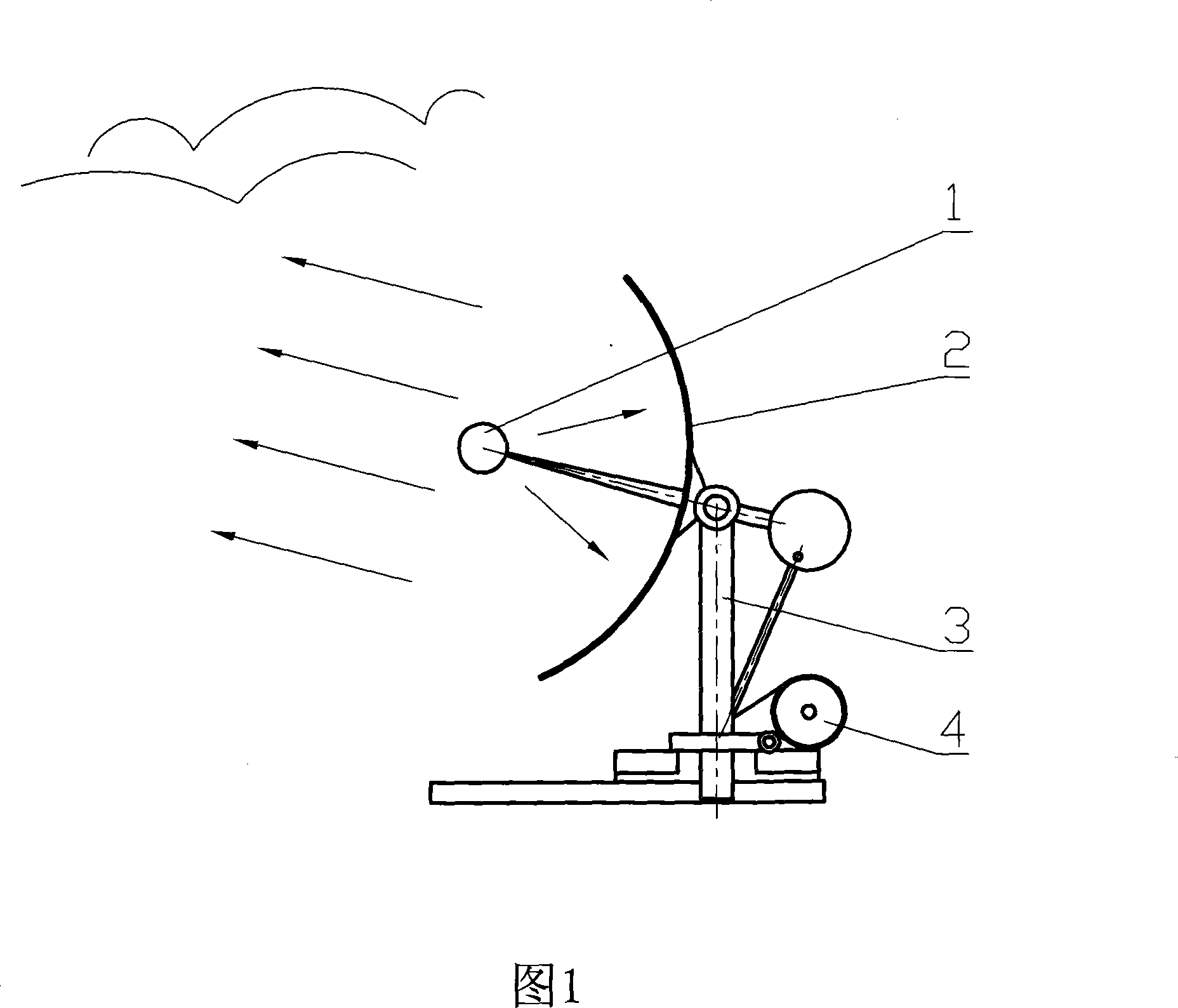
[0009] The present invention is realized in this way, as shown in Fig. 1: the infrared defogging device includes a universal bracket 3 and a motor 4, and the universal bracket 3 is connected to the base. An infrared lamp 1 and a reflector 2 are mounted on the universal bracket 3 . The reflector 2 is located between the infrared lamp 1 and the universal bracket 3 . Starting the motor 4 of the universal bracket 3 can make the infrared lamp 1 and the reflector 2 on the universal bracket 3 turn to the desired direction. When the light reflected by the infrared lamp 1 and the reflector 2 is irradiated on the fog area, the fog droplets are heated to become water vapor and rise up, and condense on the upper layer of fog droplets. Snow or hail falls. Start the motor 4 of the universal bracket 3, the infrared lamp 1 and the reflector 2 on the universal bracket 3 can be turned to the required direction, and continue to defog.

[0010] The invention can be used for large-scale demisti...


PUM


Abstract

The invention discloses an infrared demisting equipment, which comprises a universal supporting rack. The universal supporting rack is driven by a motor, and an infrared lamp and a reflector on the universal supporting rack; when the light reflected by the infrared lamp and the reflector radiates in a mist area, mist drops are heated into water vapor to ascend, the water vapor is coagulated on the mist drops on the upper layer, and when the weight of the mist drops on the upper layer is increased to the state that the suspension can not be maintained, the mist drops are formed into rain, snow or hail to fall off. The method that infrared rays are utilized to demist has the advantages that the problem that positive ions discharge does not exist, thus the security is good, and the universal supporting rack is driven by the motor, thus the infrared demisting equipment is easy to be operated. The invention can be used for the demisting in the large range in the city area, on the highway, at the air port and at the dock.

Description

technical field [0001] The invention relates to a defogging device, in particular to an infrared defogging device. Background technique [0002] Current defogging equipment utilizes positive ion generators to work. The Chinese invention patent "Local Area Positive Ion Airflow Demister and Defog Method" (application number: 01113487.9) discloses such "a local area positive ion airflow demister and demist method, the temperature sensor in the demister Convert the detected temperature signal into an electrical signal, start the high-voltage positive electricity generator through the control system to provide high-voltage electricity to the positive ion generator, and enter the defogging working state. When defogging, several single-machine combinations are used to form a barrier in a straight line , the arrangement direction forms an included angle of 90° with the wind direction, and the airflow eruption direction is consistent with the arrangement direction of the defogger an...

Claims


Application Information

Patent Timeline
Patent Type & Authority Applications(China)
IPC IPC(8): E01H13/00
Inventor 辛忻
Owner 辛忻
Why Eureka
Try Eureka