
Frequency selection in system for remote activation of vehicle functions

An active system and passive technology, applied in signal transmission system, vehicle components, anti-theft vehicle accessories, etc., can solve problems such as interference or noise sensitivity

Inactive Publication Date: 2008-06-11
LEAR CORP
View PDF0 Cites 8 Cited by
  • Summary
  • Abstract
  • Description
  • Claims
  • Application Information

AI Technical Summary

Problems solved by technology

[0009] A problem with current vehicle passive activation systems is their sensitivity to disturbance or noise

Method used


Image

  • Frequency selection in system for remote activation of vehicle functions
  • Frequency selection in system for remote activation of vehicle functions
  • Frequency selection in system for remote activation of vehicle functions

Examples


Embodiment Construction

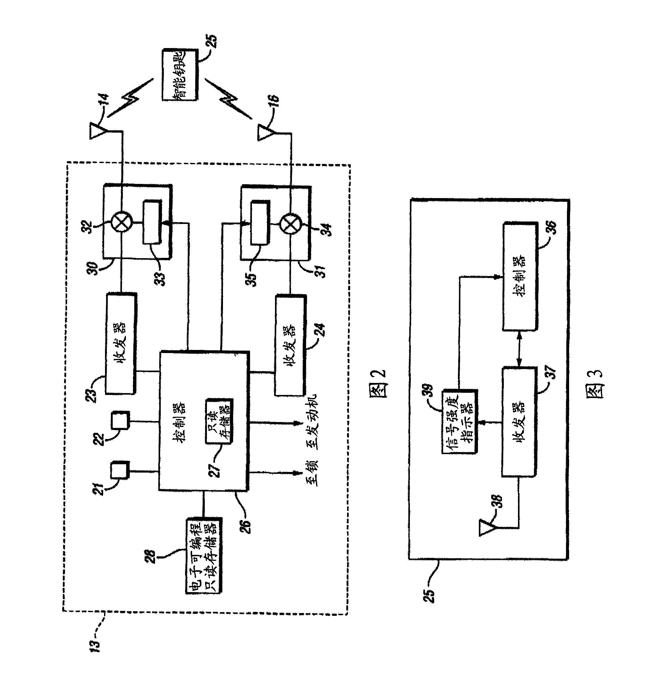
[0017] Referring to FIG. 1 , there is shown a schematic diagram of a vehicle implementing an embodiment of the present invention. Vehicle 10 has an interior area 11 and an exterior area 12 . A passive entry electronic module 13 is connected to an interior antenna 14 , which may be mounted to a vehicle dashboard 15 , for example. The module 13 can also be connected to an external antenna 16 which is preferably mounted on an external structure, such as a side view mirror housing 17 , or mounted in a door, such as the door 20 .

[0018] Door 20 may provide a partial boundary between interior area 11 and exterior area 12 . The door handle 21 includes an activation switch and a lock actuator mechanism, both of which are connected to the module 13 . By raising the door handle 21, the user issues a request to open the door, which causes the module 13 to interrogate the authorized fob. An engine start switch 22 may also be provided on the instrument panel 15 connected to the module...


PUM


Abstract

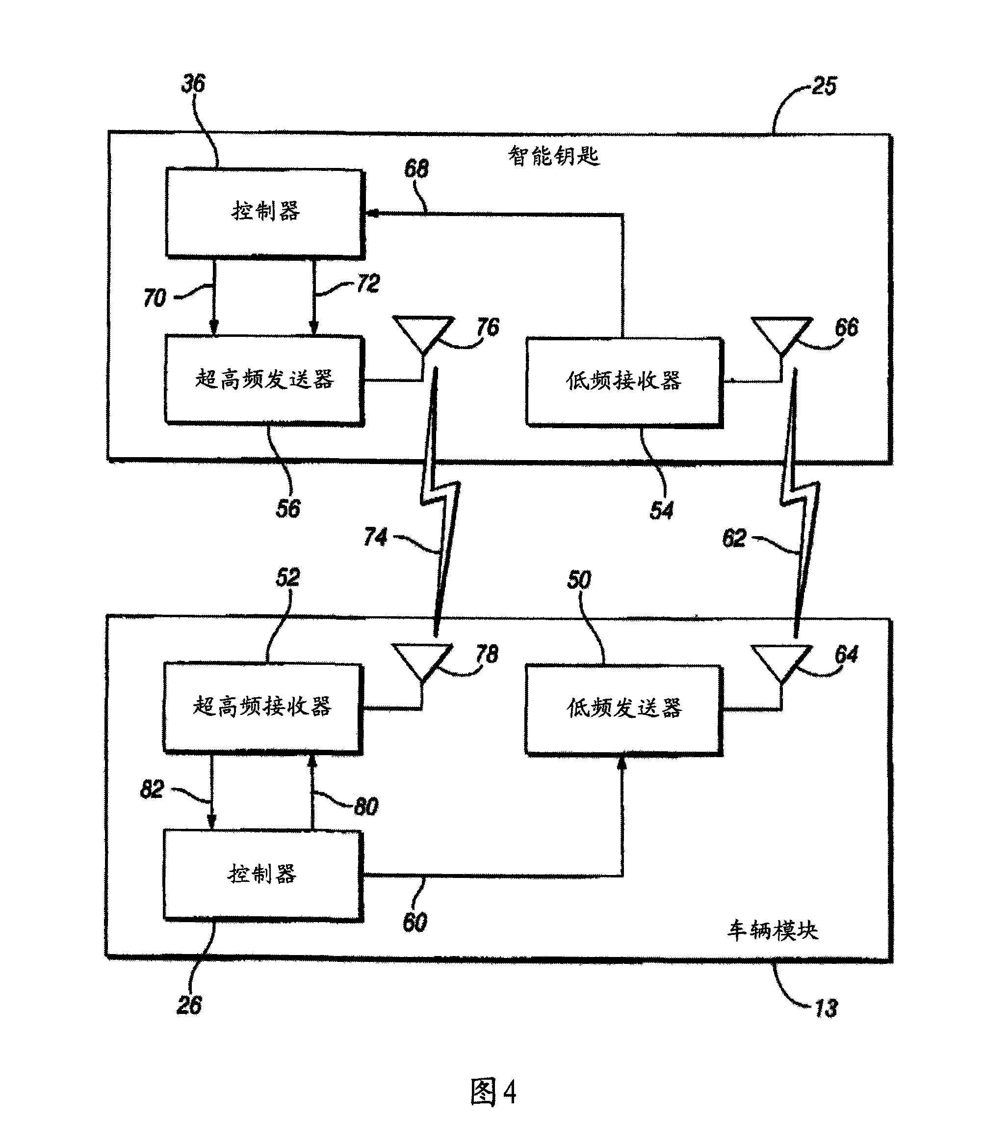
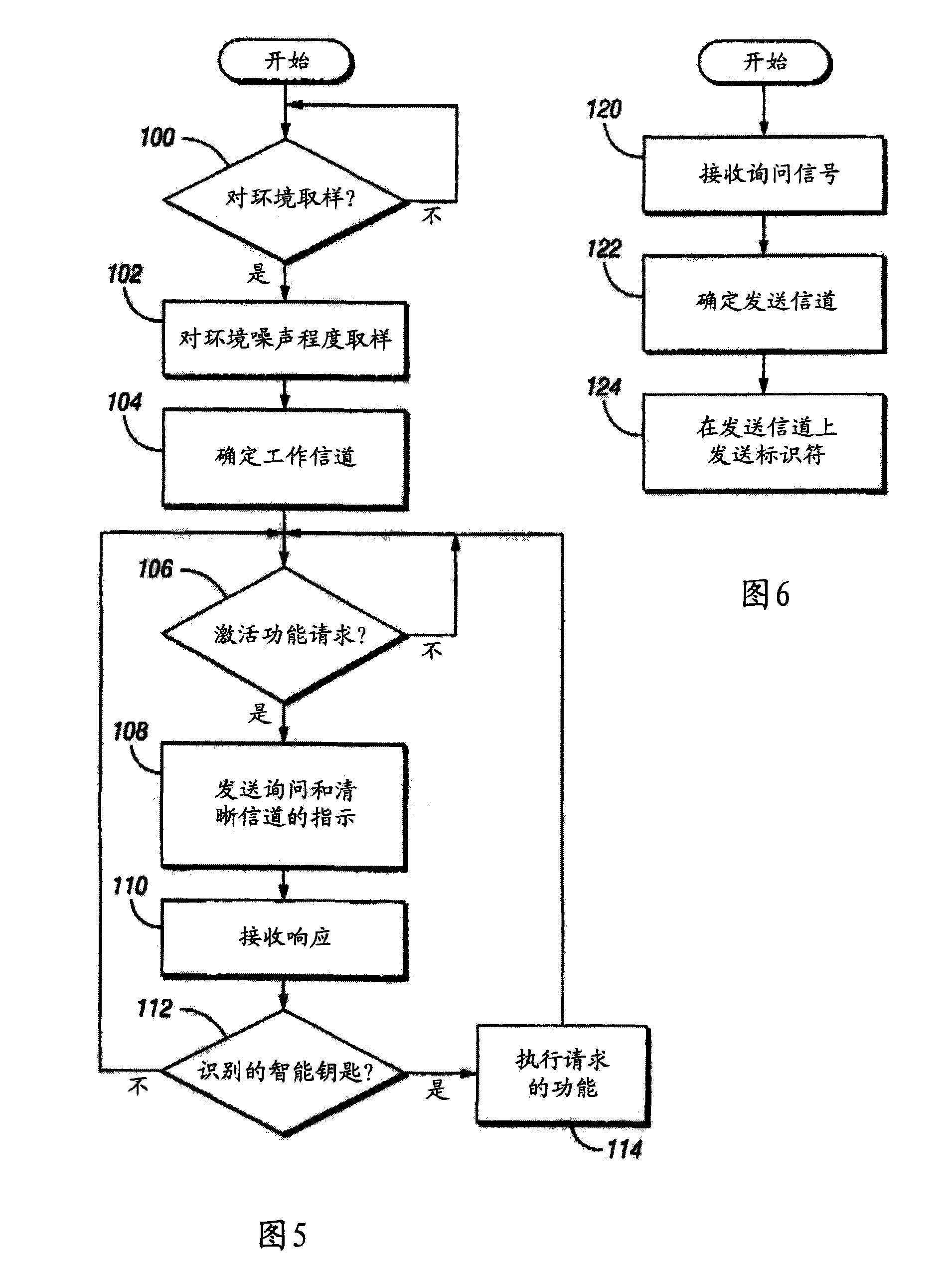
The invention relates to a method for improving the remote activation of an automotive vehicle by determining the frequency of an activation signal based on sampled ambient noise conditions. The selected frequency can be transmitted to a passive remote control device in a challenge signal. The remote control device responds with an activation signal at the selected frequency.

Description

[0001] Cross References to Related Applications [0002] This application claims the benefit of US Provisional Application No. 60 / 861,838, filed November 30,2006. Background technique [0003] The present invention generally relates to passive systems for capturing functionality in passenger vehicles. [0004] Remote vehicle activation systems, such as remote keyless entry (RKE) systems, may be active or passive in nature. In active systems, an operator typically activates a switch or button on a remote transmitter to perform a desired remote function, such as locking or unlocking a vehicle door. In passive entry systems, activation by the operator is generally not required in order to perform the desired remote control function. [0005] In a typical vehicle passive activation system, a remote transceiver, commonly referred to as a "fob" or "card", is provided. Such a smart key or card can be attached to a key fob as a stand-alone unit, or it can be the head part of an ign...

Claims


Application Information

Patent Timeline
Patent Type & Authority Applications(China)
IPC IPC(8): G08C17/00B60R25/00B60R25/24
Inventor 利雅得·哈巴尔罗纳德·O·金
Owner LEAR CORP
Learn More