Target place optimized dispatching method and system

A technology of target site and optimized scheduling, applied in elevators, transportation and packaging, etc., can solve problems such as inability to overcome, unreasonable, inaccurate number of human bodies, etc., achieve important application value and practical significance, and improve work efficiency. Effect

Active Publication Date: 2008-06-18
INST OF COMPUTING TECH CHINESE ACAD OF SCI
View PDF1 Cites 38 Cited by
  • Summary
  • Abstract
  • Description
  • Claims
  • Application Information

AI Technical Summary

Problems solved by technology

[0009] However, the defect of this device is that in the scene where the area of ​​the elevator room and the waiting hall is small and the illumination changes are relative...

Method used


Image

  • Target place optimized dispatching method and system
  • Target place optimized dispatching method and system
  • Target place optimized dispatching method and system

Examples


Embodiment approach

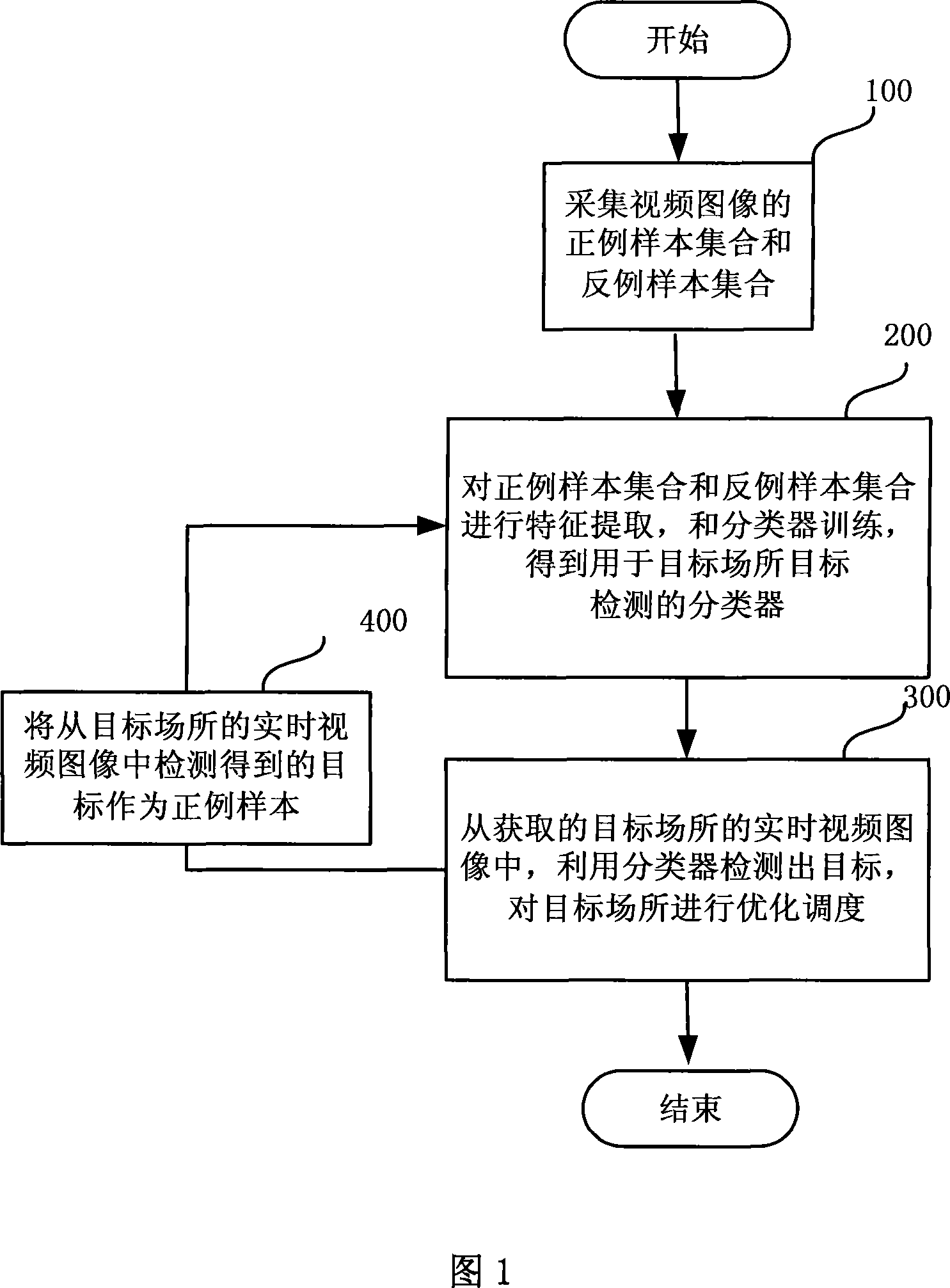
[0134] As an implementable mode, the implementation process of the method is as follows:

[0135] ●Initialize the weights, let there be m and l features of positive samples and negative samples respectively. but:

[0136] w 1 , i = 1 2 m y i = 1 1 2 l y i = 0

[0137] ● For t=1, . . . , T:

[0138] i) normalized weights, w...


PUM


Abstract

The invention discloses an objective location optimizing and scheduling method and system, which comprises the following steps: the positive sample aggregation and reverse sample aggregation opposite to the corresponding objective in the objective location are collected; in the positive sample aggregation and reverse sample aggregation, image feature is extracted and then training is performed, thereby obtaining classifier for objective inspection of objective location; in the obtained real-time video image of the objective location, the classifier is used to inspect the objective and perform optimization and scheduling of the objective location. The region of the objective inspected from the real-time video image obtained from the objective location is used as positive example, training is repeated, furthermore improving classification accuracy of the classifier, optimization and scheduling of the objective location are performed so as to improve working efficiency of the objective location.

Description

technical field [0001] The invention relates to the field of optimal scheduling, in particular to a method and system for optimal scheduling of a target site. Background technique [0002] With the development of the urbanization process and the progress of the social economy, high-rise buildings continue to emerge, which brings huge target scheduling pressure to various places. For example, today's elevator products are developing towards energy-saving and intelligent while meeting the basic needs of users. How to optimize the scheduling of passengers in the elevator room is a major issue for major elevator manufacturers and R&D personnel for target optimization scheduling. Questions to consider. [0003] The optimal scheduling of the elevator passenger target can be solved from two aspects. On the one hand, more energy-saving equipment can be used, such as more advanced dragging methods, more energy-saving motor types, etc. On the other hand, intelligent scheduling can b...

Claims


Application Information

Patent Timeline
IPC IPC(8): B66B1/06
Inventor 钱跃良刘宏高杨赵丹刘群
Owner INST OF COMPUTING TECH CHINESE ACAD OF SCI
Why Eureka
Try Eureka