
Adjustable spring mounting fastener and construction ceiling method thereof

A spring installation and adjustable technology, applied to buildings, building components, building structures, etc., to achieve the effects of reducing production energy consumption, accelerating construction speed, and high assembly level

Inactive Publication Date: 2010-06-02
北京市建筑工程装饰集团有限公司
View PDF2 Cites 0 Cited by
  • Summary
  • Abstract
  • Description
  • Claims
  • Application Information

AI Technical Summary

Problems solved by technology

[0003] The purpose of the present invention is to provide an adjustable spring installation buckle and its building ceiling method, to solve the problem of the assembled connection between the keel and the ceiling board and the overall two-way adjustment

Method used


Image

  • Adjustable spring mounting fastener and construction ceiling method thereof
  • Adjustable spring mounting fastener and construction ceiling method thereof
  • Adjustable spring mounting fastener and construction ceiling method thereof

Examples


Embodiment Construction

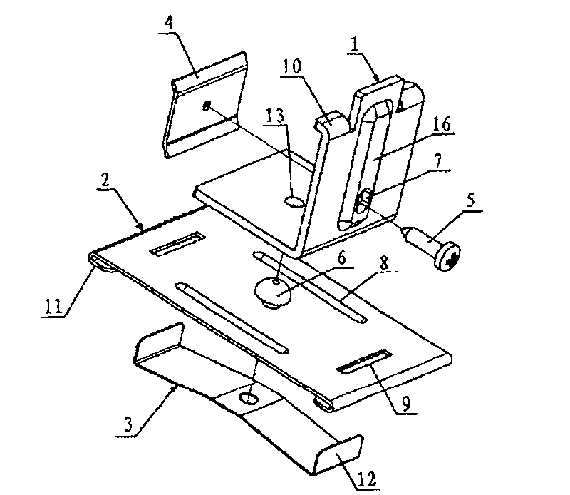
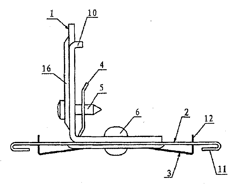
[0030] Examples see figure 1 , 2 As shown, this adjustable spring mounting buckle is connected between the ceiling keel and the ceiling board, and it includes an L-shaped plate 1, a clamping plate 2, a spring leaf 3, a limiting plate 4, screws 5 and rivets 6.

[0031] The middle part of the top edge of the L-shaped plate 1 is a straight edge, and both sides are bent edges 10, and the horizontal plate has a rivet hole 13, and the vertical plate has a screw hole 7. There is a protrusion 16 on the outer surface of the vertical plate of the above-mentioned L-shaped plate 1 .

[0032] The clamping plate 2 is rectangular, with a rivet hole in its center, downwardly bent draw-in grooves 11 on both sides, and two strip holes 9 symmetrically formed on the board surface on both sides of the rivet hole. The clamping plate 2 is symmetrically provided with two oval slotted holes 8 on the other two sides of the rivet hole.

[0033] The middle part of spring leaf 3 is plane and has rivet ...


PUM


Abstract

The invention provides an adjustable spring mounting clasp, which is connected between the ceiling joist and the ceiling plate. The middle part of the L-shaped plate is a straight edge, while the twoterminal parts are bending edges. The horizontal plate is provided with a rivet hole, while the vertical plate is provided with a screw hole. The middle part of the clamping groove is provided with arivet hole, and the two lateral parts are provided with a neck bending downward, wherein two stripy holes are arranged symmetrically at the two sides of the rivet hole in the clamping groove. The middle part of the spring plate is a plane which is provided with a rivet hole, while the two sides are both provided with a crochet, and a symmetrical inclined plane shaped like the ichnography of a hornis arranged between the middle part and the two crochets. The middle part of the retaining plate is provided with a screw hole, the top edge and the bottom edge are both provided with a flanging, wherein the bottom flanging bends toward the interior of the vertical plate of the L-shaped plate, and the top flanging bends toward the exterior of the vertical plate of the L-shaped plate. The interiorof the vertical plate of the L-shaped plate is connected with the retaining plate horizontally via a screw; the horizontal plate of the L-shaped plate, the clamping plate and the spring plate are connected downward sequentially via rivets. The invention has the characteristics of high precision and good flexibility of construction, rapid construction, fabricated installation, etc, and is widely applied in ceiling construction of various structures.

Description

(1) Technical field [0001] The invention relates to an L-shaped board for a suspended ceiling of a building ceiling board. (2) Background technology [0002] Terminal 3 of the Capital International Airport is one of the important projects of the 2008 Beijing Olympic capital construction project, and it is the first international hub airport terminal in China. The roof truss of the building is a super large two-way curved steel grid structure. The curvature of the roof changes when it rotates. The two-way maximum arc is 23rad, and the minimum arc is 1.2rad. The triangular ceiling plate is attached to the lower chord of the roof truss. Beautiful and smooth. The total area of ​​the suspended ceiling project is 104,124 square meters, among which the high and low internal space and the curved roof are one of the important features of the project. In the ceiling decoration project of the terminal building, the difficulty is that welding cannot be used for each joint, and each jo...

Claims


Application Information

Patent Timeline
Patent Type & Authority Patents(China)
IPC IPC(8): E04B9/22
Inventor 张春雷付文张耀辉张帆徐峰
Owner 北京市建筑工程装饰集团有限公司
Learn More